Industrial oil cooker fire protection system

Inactive Publication Date: 2010-09-07
YEN PING LI
View PDF9 Cites 31 Cited by
  • Summary
  • Abstract
  • Description
  • Claims
  • Application Information

AI Technical Summary

Benefits of technology

[0003]It is a major object of the invention to provide method and apparatus to efficiently and effectively suppres

Problems solved by technology

These fires are difficult to exti

Method used


Image

  • Industrial oil cooker fire protection system
  • Industrial oil cooker fire protection system
  • Industrial oil cooker fire protection system

Examples


Example

[0020]FIG. 1 is a schematic perspective view of an industrial oil cooker system;

[0021]FIG. 2 is a vertical section taken through the FIG. 1 system oil pan and hood;

[0022]FIG. 2a is a modification;

[0023]FIG. 3 is a schematic top plan view of a cooker pan, and location of water mist nozzles, longitudinally and laterally;

[0024]FIG. 4 is an elevational view showing a nozzle at selected and selectable angle, vertically; and

[0025]FIG. 5 is a view like FIG. 1, but showing a modification.

DETAILED DESCRIPTION

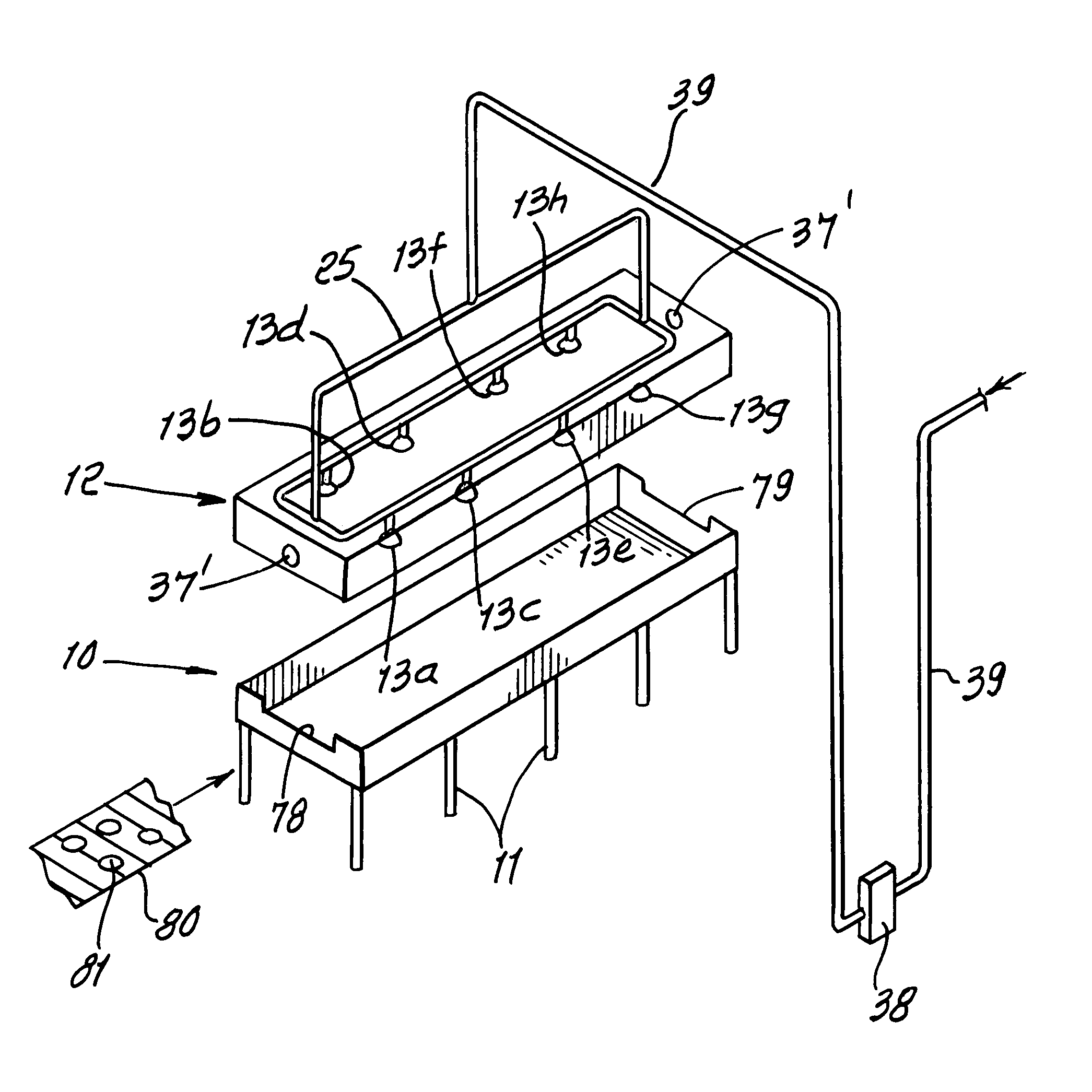
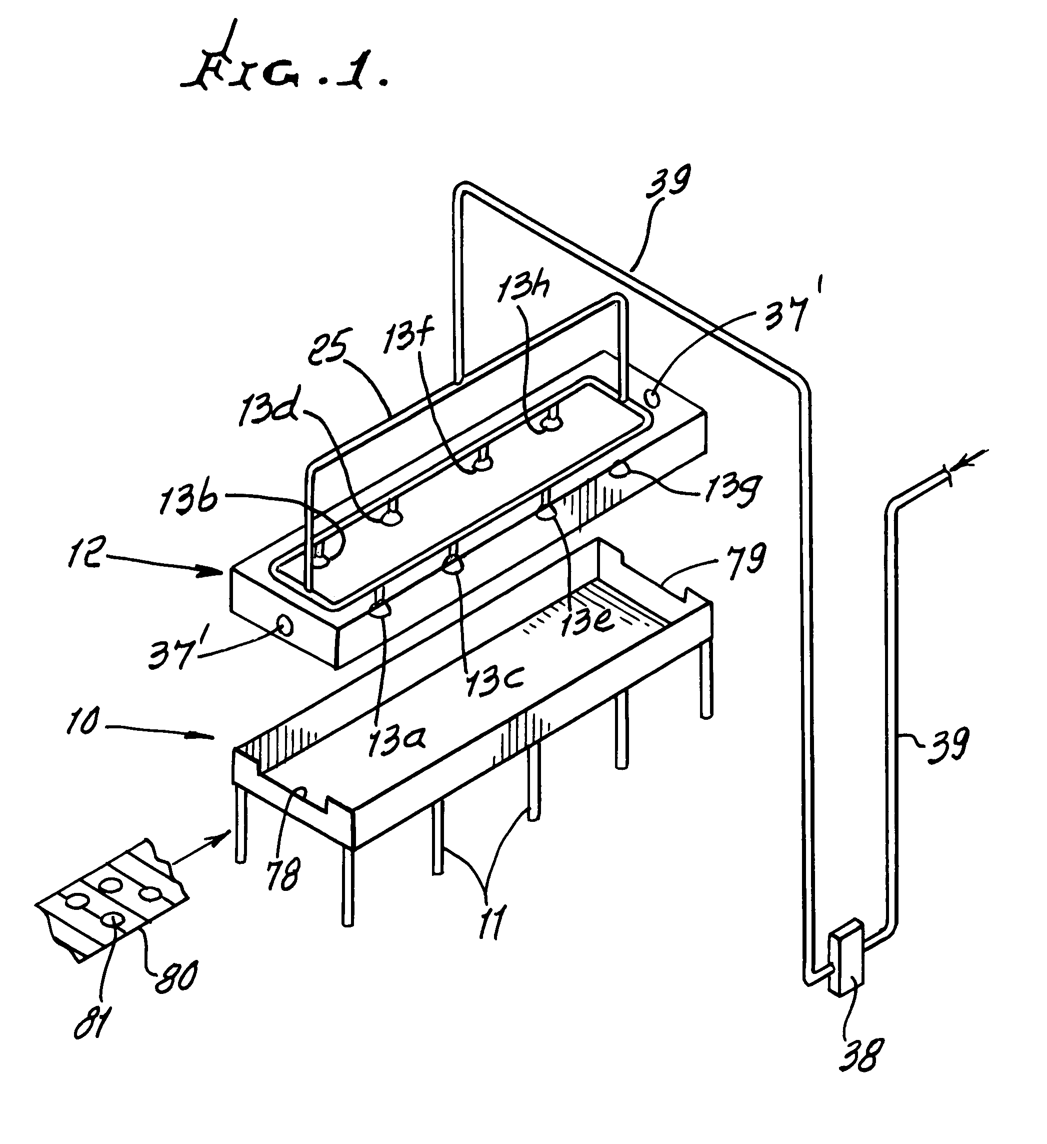
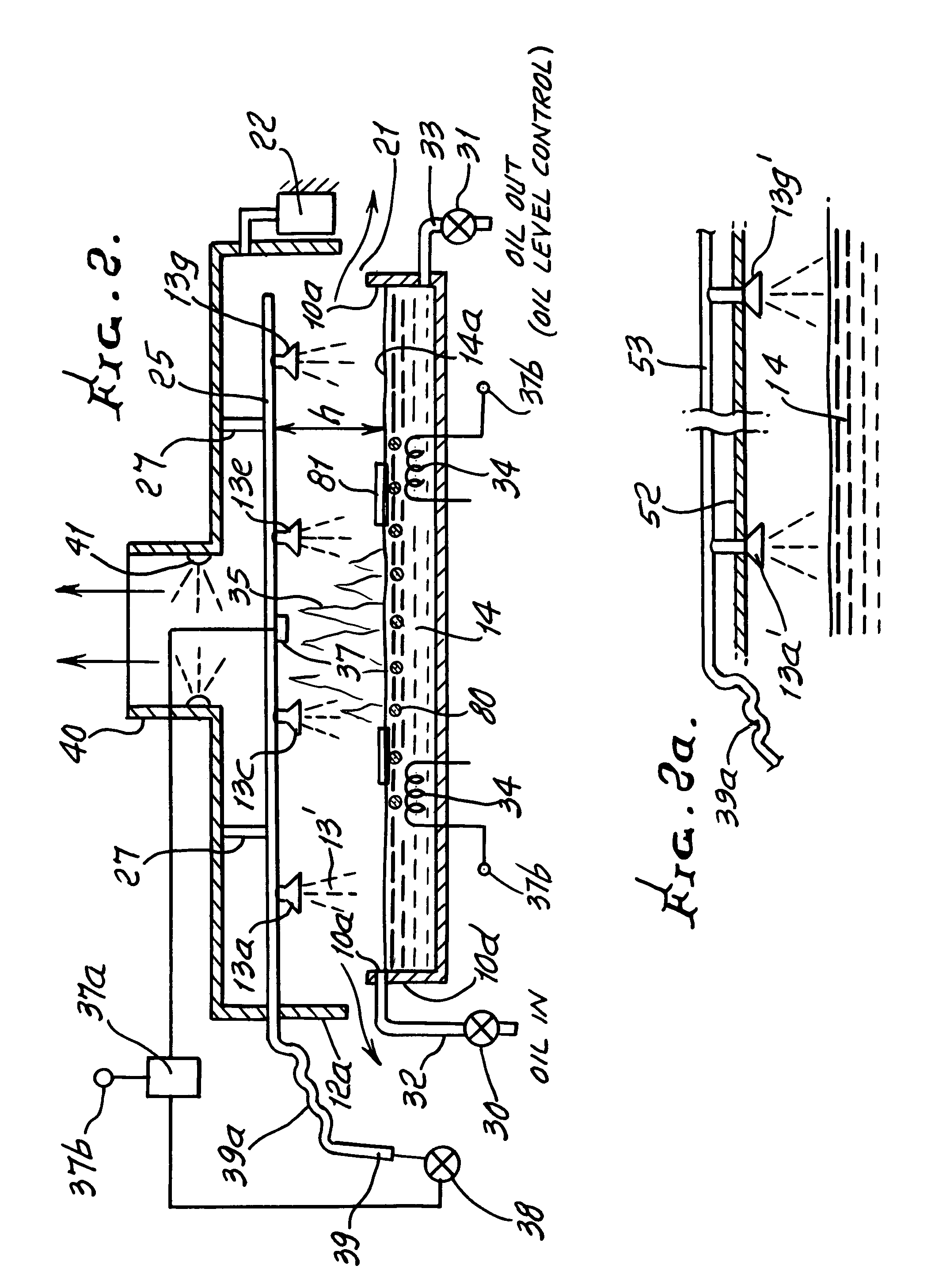
[0026]Referring first to FIG. 1, it shows a longitudinally elongated cooker pan 10 supported on legs 11; a longitudinally elongated hood 12 directly above the pan; and mist producing or forming nozzles. The latter include a first pair of laterally spaced nozzles 13a and 13b; a second pair of laterally spaced nozzles 13c and 13d; a third pair of laterally spaced nozzles 13e and 13f; and a fourth pair of laterally spaced nozzles 13g and 13h. See also FIG. 3, showing nozzles in two longitud...


PUM


Abstract

A cooker system, comprising a relatively wide pan containing cooking oil at high temperatures, the pan extending longitudinally, for cooking edibles located longitudinally, single or multiple row water mist producing nozzles supported above the pan, there being one or more laterally spaced nozzles at longitudinally spaced locations above the pan, each nozzle producing mist substantially covering an area of at least about one square foot, at oil surface level in the pan, and control means to control pressurized water delivery to the nozzles, in the event of fire in or associated with oil in the pan.

Description

BACKGROUND OF THE INVENTION[0001]This invention relates generally to suppression of accidental fires involving cooking oil or fat as in industrial oil cookers, and more particularly concerns employment of pure water mist in such suppression, as well as extinction of such fires. Fires in the majority of these large cookers involve liquid cooking oil or fat fires. These fires are difficult to extinguish and are easily re-ignited.[0002]There is great need for improvements in methods and means for suppressing such fires, extreme danger from fire resulting from the large sizes of such cookers.SUMMARY OF THE INVENTION[0003]It is a major object of the invention to provide method and apparatus to efficiently and effectively suppress such fires, through use of water mist. Such mists are non-toxic, and do not contribute to environmental problems.[0004]Basically, the invention provides a method of extinguishing a fire characterized by production of flames openly rising above an upwardly presen...

Claims


Application Information

Patent Timeline
IPC IPC(8): A62C3/00A47J37/12A62C37/36A47J36/00A62C37/10
CPCA47J37/1266A62C3/06A62C37/10A62C37/44
Inventor YEN, PING LI
Owner YEN PING LI
Why Eureka
Try Eureka