Electrical wiring device with a center nightlight and a plurality of safety features

a technology of safety features and wiring devices, applied in the direction of connection of coupling devices, connection contact materials, electrical apparatus casings/cabinets/drawers, etc., can solve the problems of fire, shock or electrocution, certain types of faults known to occur in branch electric circuits and electrical wiring systems,

Active Publication Date: 2010-09-07
PASS SEYMOUR
View PDF38 Cites 32 Cited by
  • Summary
  • Abstract
  • Description
  • Claims
  • Application Information

AI Technical Summary

Problems solved by technology

Certain types of faults are known to occur in branch electric circuits and electrical wiring systems.
These faults represent serious safety issues that may result in fire, shock or electrocution if not addressed properly.
The circuit interrupter provides power to the load terminals under normal conditions, but breaks electrical connectivity when the protective device detects a fault condition in the load circuit.
Unfortunately, conventional wiring devices are not equipped to repel such things.
In the event that water is applied, whether by design or by accident, a live wiring device may become a shock hazard.
Conventional wiring devices have other drawbacks.
Even if the moisture level does not constitute a shock hazard, corrosion may develop over time.
A conventional wiring device may also degrade in a dusty environment, or be compromised by insect infestation.
A conventional protective wiring device includes sensitive circuitry that makes these devices particularly vulnerable to contaminants.
Such air drafts may compromise the energy efficiency of the structure.
Another safety issue relates to the insertion of foreign objects into receptacle openings.
Unfortunately, this scenario often results in an electric shock, burns, or electrocution.
Another safety issue that is of great concern relates to the amount of ambient lighting in a given room or space.
On the other hand, the darkened room represents a safety issue.
For example, if an object is disposed relatively low to the floor surface the person may trip over it and suffer an injury.
There are situations where a light switch is not available, or is not readily available.
A person entering a darkened theatre would expect to incur the wrath of his fellow patrons if he turned the theatre lights ON while finding a seat.
The most obvious drawback in getting the portable nightlight into a socket in a darkened room is finding the socket in the first place.
On the other hand, once the night light is inserted into the receptacle, it may remain there day and night for an extended period of time and represent a waste of energy.
Unfortunately, the resident may forget to plug the light back into the socket until after night fall and finds himself revisiting the darkened room scenario.
In addition, once a small night light is unplugged from the receptacle there is the possibility that it will become lost, misplaced, or damaged from excessive handling.
While this approach obviates some of the drawbacks described above, there are other drawbacks that come into play.
Conventional permanent lighting elements such as incandescent and neon lights have a relatively short life expectancy of only a few years and, therefore, require periodic servicing and / or replacement.
This problem is exacerbated by the fact that the light is typically hard-wired to power contacts disposed in the wiring device.
As such, the light element is permanently ON, further limiting the light elements life expectancy of the device.
One design problem associated with using a light sensor to selectively actuate the light element relates to providing a proper degree of isolation between the light sensor and the light element.
Accordingly, conventional devices of this type often fail to provide an adequate amount of illumination for the intended application and, therefore, do not address the safety concern in a satisfactory manner.

Method used


Image

  • Electrical wiring device with a center nightlight and a plurality of safety features
  • Electrical wiring device with a center nightlight and a plurality of safety features
  • Electrical wiring device with a center nightlight and a plurality of safety features

Examples


first embodiment

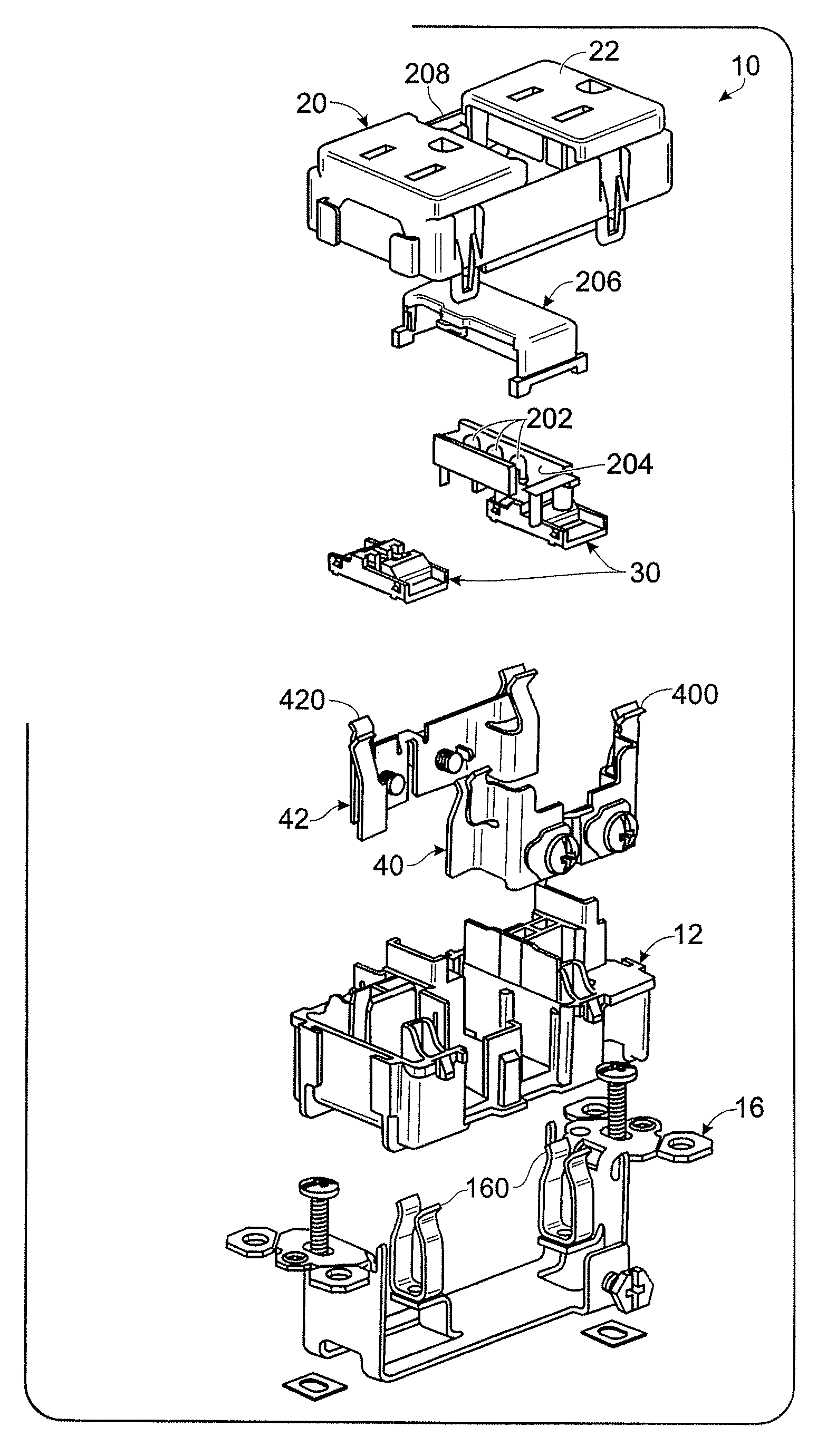
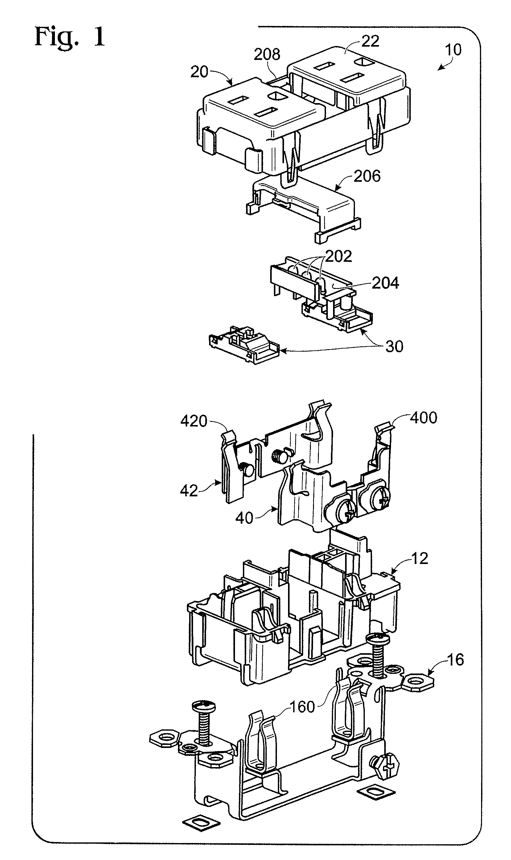
[0029]As embodied herein and depicted in FIG. 1, an exploded view of the device 10 in accordance with the present invention is disclosed. Device 10 includes a receptacle outlet device with center night light assembly 200. Cover member includes receptacle openings 22 disposed at either end. In the central portion, opening 208 is formed therein. Opening 208, of course, is configured to accommodate lens element 206. The lens 206 is configured to mate with reflector member 204 which includes white LEDs 202 disposed therein. The LEDs 202 are connected to pig tailed wires connected across receptacle terminal structures 40, 42. Of course, the cover member 20 also accommodates shutters 30.

[0030]The hot and neutral receptacle terminals (40, 42) are disposed within back body member 12. When the ground strap structure 16 is inserted into body member 12 from behind, the hot receptacle terminals 420, the neutral receptacle terminals 400, and the ground terminals 160 are perfectly aligned with th...

second embodiment

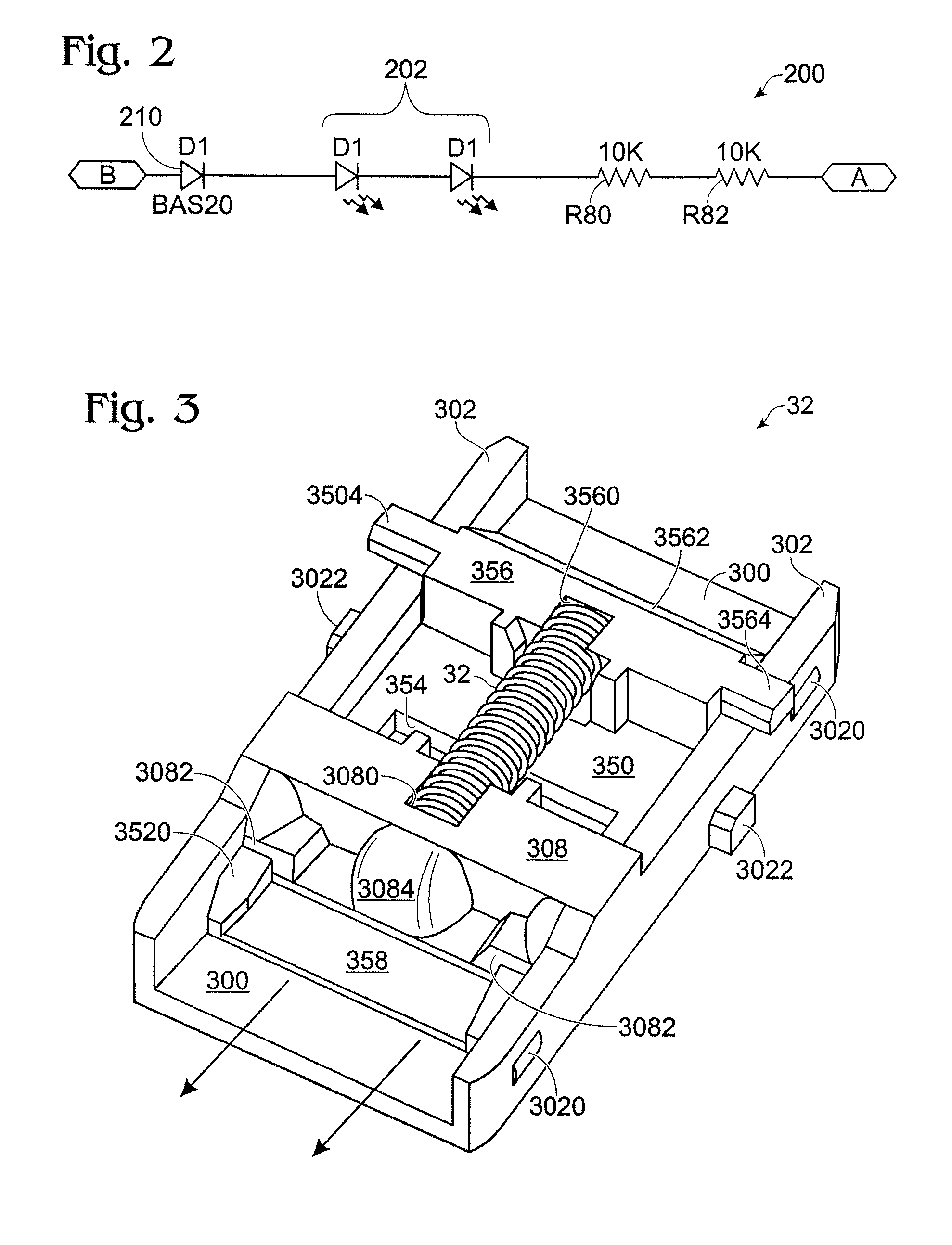
[0043]Referring to FIG. 5, a schematic of the center night light assembly in accordance with the present invention is shown. Again, the satellite PCB 201 receives power from the receptacle terminals 30, 32, which are connected at points “A” and “B”, respectively. When the ambient light is above a certain level, light sensor 212 reacts to the ambient light level and diode D3 begins to conduct. In one embodiment, sensor 212 is implemented using a light sensing diode and the amount of current conducted by sensor 212 is related to the amount of incident ambient light. As the ambient light increases past a predetermined level, which may be adjusted by potentiometer R6 in the factory, the Darlington transistor pair (Q1, Q2) are turned OFF. In particular, the current flow through D4 pulls down the base of transistor Q1. Q1, in turn, pulls down the base of Q2. When the ambient light begins to decrease, e.g., as night falls, the current flowing through sensor 212 begins to decrease according...

fifth embodiment

[0046]FIG. 6 is a perspective view of the fully assembled device in accordance with the present invention. The front cover 20 of the device includes light assembly lens 206 and sensor lens 207. Both lens elements (206, 207) are substantially flush with the surface of the cover 20.


PUM


Abstract

The present invention is directed to an electrical wiring device that includes a housing having a plurality of line terminals and a plurality of load terminals. A cover assembly includes a first set of receptacle openings and a second set of receptacle openings. A plurality of receptacle terminals are disposed in the housing and coupled to the plurality of load terminals. A first protective shutter assembly is disposed in the cover assembly between the first set of receptacle openings and the first set of receptacle terminals and a second protective shutter assembly disposed in the cover assembly between the second set of receptacle openings and the second set of receptacle terminals. A light assembly is disposed in a central portion of the cover assembly between the first set of receptacle openings and the second set of receptacle openings. The light assembly has a light transmission region occupying a substantial portion of a width of the cover assembly.

Description

CROSS-REFERENCE TO RELATED APPLICATIONS[0001]This is a continuation-in-part of U.S. patent application Ser. No. 11 / 609,793 filed on Dec. 12, 2006 and U.S. patent application Ser. No. 11 / 294,167 filed on Dec. 5, 2005, which is a continuation-in-part of U.S. patent application Ser. No. 11 / 242,406 (Now U.S. Pat. No. 7,285,721) filed on Oct. 3, 2005, which is a continuation application of U.S. patent application Ser. No. 10 / 726,128 filed on Dec. 2, 2003 (now U.S. Pat. No. 6,989,489), the contents of which are relied upon and incorporated herein by reference in its entirety, and the benefit of priority under 35 U.S.C. §120 is hereby claimed, U.S. patent application Ser. No. 10 / 726,128 claims the benefit of priority under 35 U.S.C. §119(e) to U.S. Provisional Patent Application 60 / 439,370 filed Jan. 9, 2003.BACKGROUND OF THE INVENTION[0002]1. Field of the Invention[0003]The present invention relates generally to electrical wiring devices, and particularly to electrical wiring devices havi...

Claims


Application Information

Patent Timeline
Patent Type & Authority Patents(United States)
IPC IPC(8): H02G3/08H02H3/00H02H9/00
CPCH01R13/4534H01R13/665H01R13/717H01R13/6658H01R13/6666H01R13/6683H01R13/713H01R13/7175
Inventor WEEKS, RICHARDRICHARDS, JEFFREY C.WILSON, GARY O.SAVICKI, JR., GERALD R.
Owner PASS SEYMOUR
Why Eureka
Try Eureka