Apparatus for assisting write operation using high frequency magnetic field in disk drive

a technology of high frequency magnetic field and disk drive, which is applied in the field of disk drive, can solve the problems of inability to easily promote ultra-high recording density, method problems, and inability to reduce coercive force at the recording part,

Active Publication Date: 2010-09-07
KK TOSHIBA
View PDF5 Cites 65 Cited by
  • Summary
  • Abstract
  • Description
  • Claims
  • Application Information

AI Technical Summary

Problems solved by technology

However, the ultra-high recording density cannot be easily promoted due to the thermal fluctuation that is inherent to magnetic recording.
This method has a problem, however.
Consequently, the coercive force can hardly be reduced at the recording part, rendering it difficult to accomplish high frequency assisted writing.
Therefore, the area in which the high-frequency magnetic field emanating from the STO works is limited to within a radius of only tens of nanometers from the STO.
However, the high frequency assisted writing method using an STO has been found to be disadvantage in the following respect.
This ultimately hinders stable, high-quality, high frequency assisted writing.

Method used


Image

  • Apparatus for assisting write operation using high frequency magnetic field in disk drive
  • Apparatus for assisting write operation using high frequency magnetic field in disk drive
  • Apparatus for assisting write operation using high frequency magnetic field in disk drive

Examples


first embodiment

[0035](Configuration of the Disk Drive)

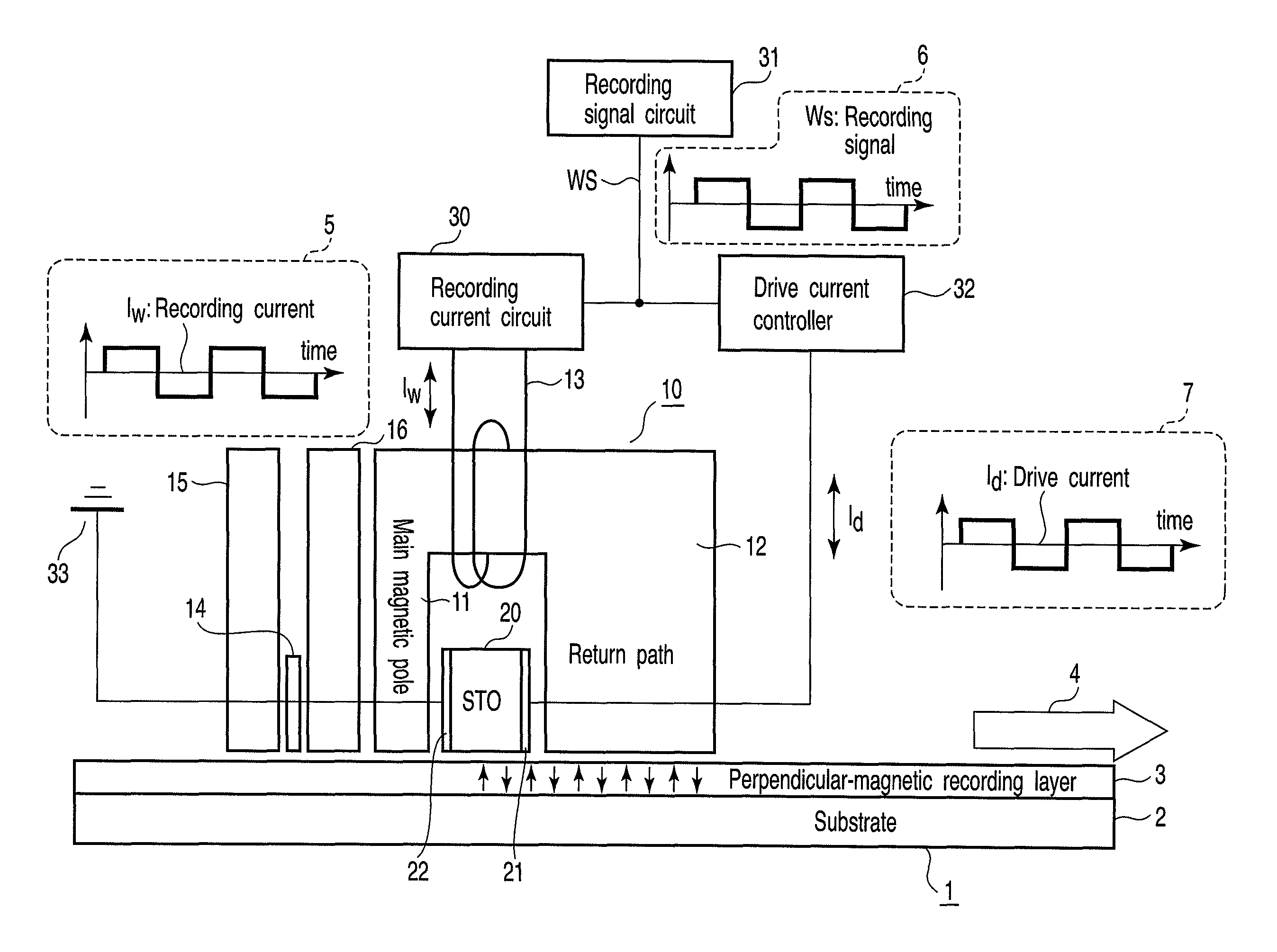
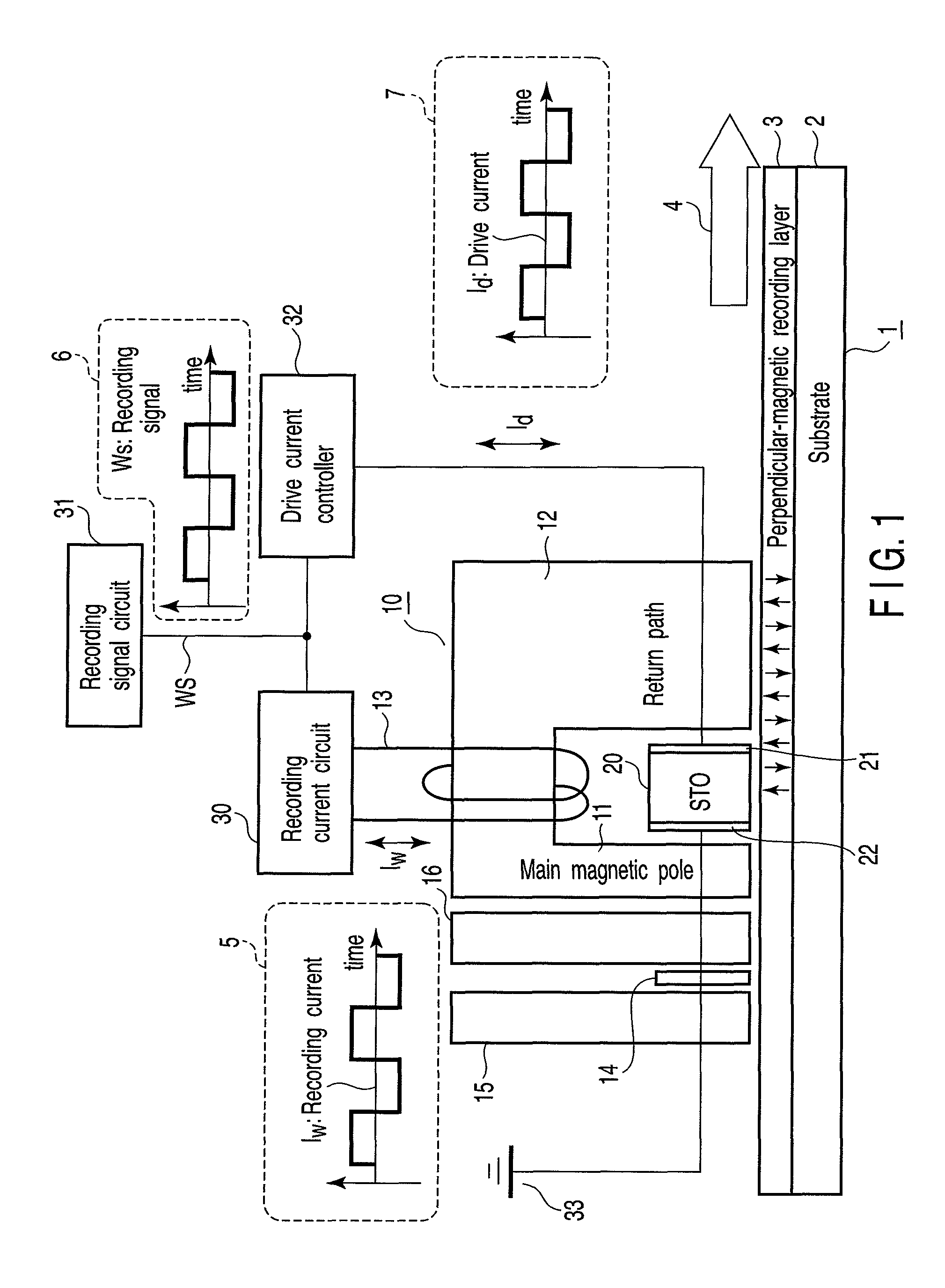
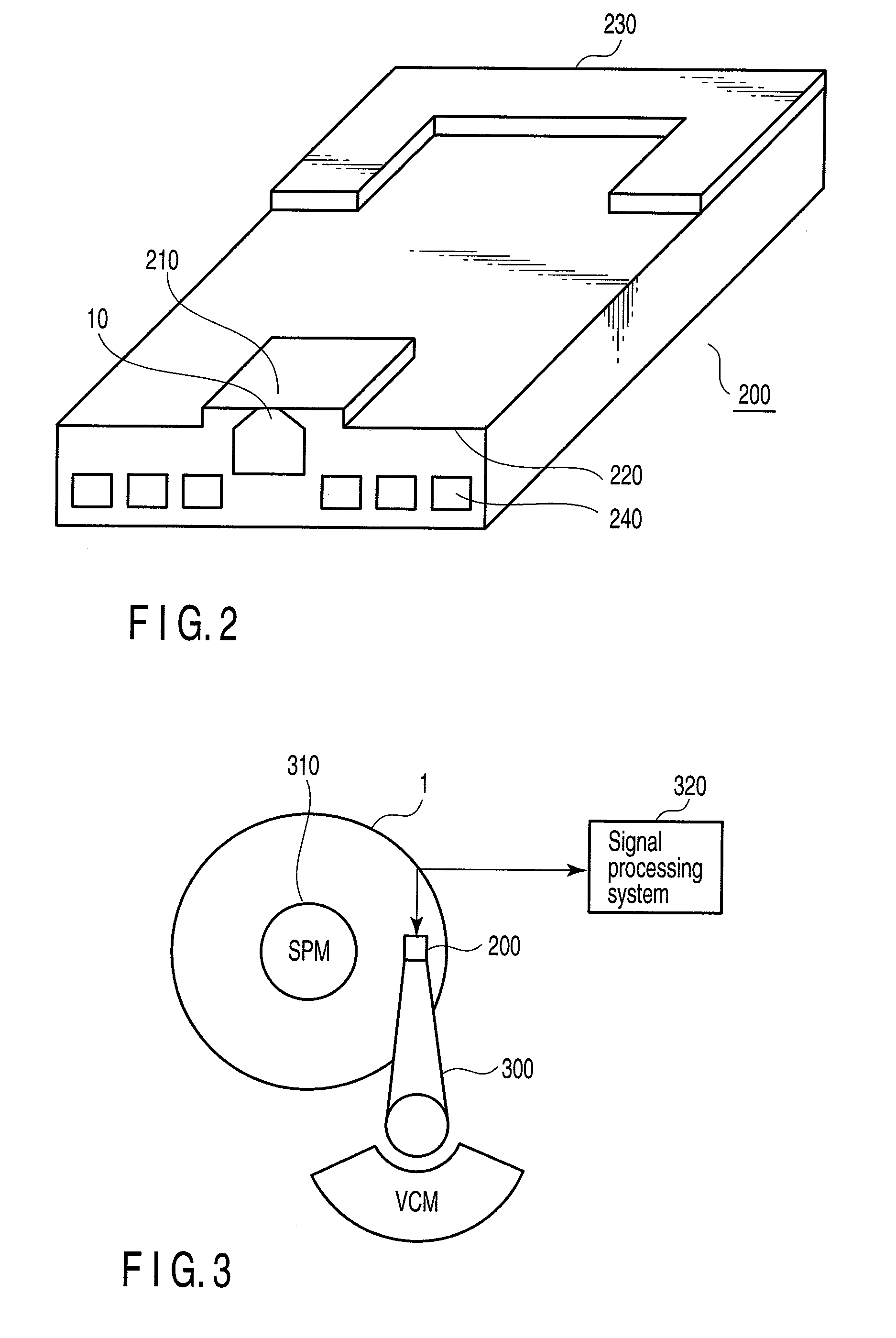
[0036]FIG. 1 is a diagram showing the major components of a disk drive according to a first embodiment of the present invention. FIG. 2 is a diagram explaining the structure of the head slider according to this embodiment. FIG. 3 is a diagram schematically illustrating the configuration of the disk drive according to this embodiment. FIG. 4 is a diagram showing the structure of the spin torque oscillator incorporated in the first embodiment.

[0037]The disk drive according to the present embodiment has a disk 1 and a magnetic head 10. The disk 1 is a perpendicular-magnetic recording medium. The magnetic head 10 has the function of performing high frequency assisted writing. As FIG. 2 shows, the magnetic head 10 is mounted on the distal end of a head slider 200 and located near a surface 210 that faces the disk 1.

[0038]The head slider 200 is made of a composite material composed of, for example, aluminum oxide (Al2O3) and titanium carbide (TiC). T...

second embodiment

[0074]FIG. 12 is a diagram showing the major components of a disk drive according to a second embodiment of the present invention. Of the components shown in FIG. 12, those identical to the components shown in FIG. 1 are designated by the same reference numbers and will not be described in detail.

[0075]In the first method described above, bias magnetic fields, each having a specific intensity, are applied to the oscillation layer 25 of the STO 20, respectively from the bias layer (layer 25b shown in FIG. 4) and the spin injection layer 23. Therefore, a DC drive current (IdDC) of a prescribed value corresponding to the operating point shown in FIG. 8 should be supplied to the oscillation layer 25 to make the layer 25 oscillate at a prescribed frequency even if it is applied with no leakage recording magnetic field Hex from the main magnetic pole 11.

[0076]In view of this, the drive current controller 32 is configured to supply a drive current Id (=IdAC+IdDC) to the STO 20 in the prese...

third embodiment

[0079]FIG. 13 is a diagram showing the major components of a disk drive according to a third embodiment of the present invention. Of the components shown in FIG. 13, those identical to the components shown in FIG. 1 are designated by the same reference numbers and will not be described in detail.

[0080]In the second method described above, the drive current Id supplied to the STO 20 must be inverted in polarity in synchronism with the polarity inversion of the recording current Iw in order to stabilize the oscillation frequency of the STO 20. In addition, the drive current Id must be changed in amplitude, depending upon the polarity of the driving current Id.

[0081]In the present embodiment, the drive current controller 32 is configured to supply a drive current Id (=IdAC+IdDC) to the STO 20. The current Id changes in synchronism with the changes of the recording signal Ws and recording current Iw and changes in amplitude in accordance with its polarity.

[0082]The recording signal circ...


PUM

PropertyMeasurementUnit
oscillation frequencyaaaaaaaaaa
recording currentaaaaaaaaaa
polarityaaaaaaaaaa

Abstract

According to one embodiment, a disk drive having a spin torque oscillator and designed to perform high frequency assisted writing. The disk drive has a magnetic disk, a magnetic head, a coil, and a drive current controller. The drive current controller controls a drive current to supply to the spin torque oscillator. To record data magnetically in the disk, the drive current controller supplies to the spin torque oscillator the drive current that changes in synchronism with the polarity inversion of the recording current supplied to the coil, which excites the recording magnetic pole of the magnetic head.

Description

CROSS-REFERENCE TO RELATED APPLICATIONS[0001]This application is based upon and claims the benefit of priority from Japanese Patent Application No. 2007-230475, filed Sep. 5, 2007, the entire contents of which are incorporated herein by reference.BACKGROUND[0002]1. Field[0003]One embodiment of the present invention relates to a disk drive that employs an assisted writing method using a high-frequency magnetic field.[0004]2. Description of the Related Art[0005]In the field of disk drives, a representative example of which is a hard disk drive, magneto-resistive (MR) elements and giant magneto-resistive effect (GMR) elements have recently been put to practical use as read-head elements for use in magnetic heads. The MR element and the GRM element have remarkably increased the recording capacity of the disk drive. Further, the ultra-high recording density in the disk drive is promoted by utilizing perpendicular magnetic recording, because perpendicular magnetic recording can, in princi...

Claims


Application Information

Patent Timeline
Patent Type & Authority Patents(United States)
IPC IPC(8): G11B5/02
CPCG11B5/02G11B5/1278G11B5/314G11B2005/0005G11B2005/0024
Inventor TAKEO, AKIHIKOAKIYAMA, JUNICHIYAMADA, KENICHIROIWASAKI, HITOSHITAKAGISHI, MASAYUKIFUNAYAMA, TOMOMITAKASHITA, MASAHIROSHIMIZU, MARIKO
Owner KK TOSHIBA
Why Eureka
Try Eureka