Fusing apparatus and electrophotographic image-forming apparatus having the same

a technology of electrophotographic image and forming apparatus, which is applied in the direction of electrographic process apparatus, ohmic resistance heating, instruments, etc., can solve the problem that the fusing apparatus takes a considerable long warm-up time to reach the fusing temperature, and achieves a small thermal capacity, reduce and reduce the effect of the first print-out tim

Inactive Publication Date: 2010-09-07
HEWLETT PACKARD DEV CO LP
View PDF16 Cites 22 Cited by
  • Summary
  • Abstract
  • Description
  • Claims
  • Application Information

AI Technical Summary

Benefits of technology

[0012]The present general inventive concept provides a fusing apparatus including a rotatable belt having a small thermal capacity so that a warm-up time can be shortened by directly radiating heat from a heat source to a nip, thereby reducing a first print out time (FPOT), and an electrophotographic image forming apparatus including the fusing apparatus.

Problems solved by technology

The fusing apparatus having the above-described structure has a large thermal capacity, and thus the fusing apparatus takes a considerably long warm-up time to reach the fusing temperature when power is supplied for printing.

Method used


Image

  • Fusing apparatus and electrophotographic image-forming apparatus having the same
  • Fusing apparatus and electrophotographic image-forming apparatus having the same
  • Fusing apparatus and electrophotographic image-forming apparatus having the same

Examples


Embodiment Construction

[0041]Reference will now be made in detail to embodiments of the present general inventive concept, examples of which are illustrated in the accompanying drawings, wherein like reference numerals refer to the like elements throughout. The embodiments are described below in order to explain the present general inventive concept by referring to the figures.

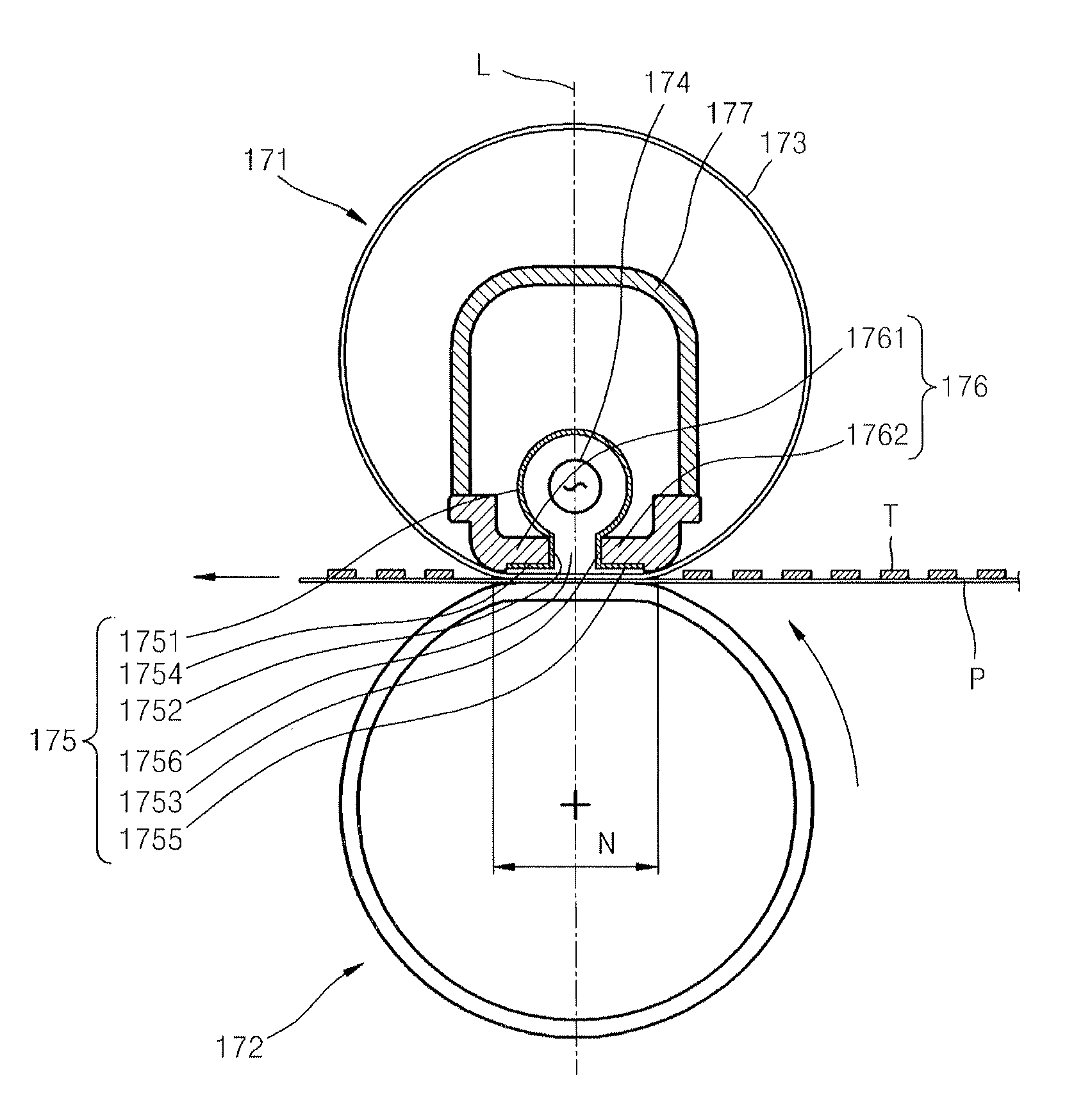
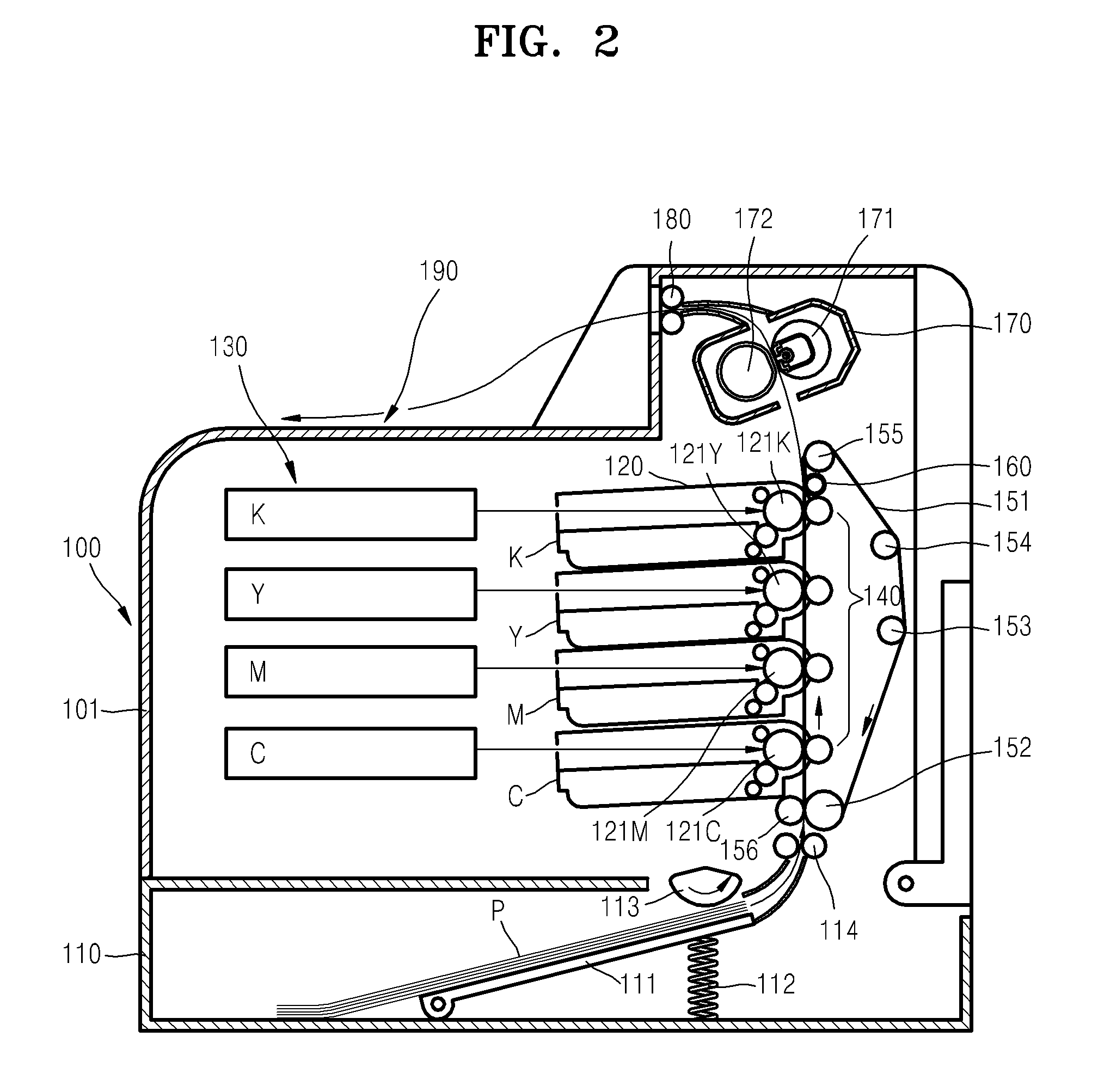
[0042]FIG. 2 is a lateral cross-sectional view illustrating an electrophotographic image forming apparatus 100 including a fusing apparatus according to an embodiment of the present general inventive concept; FIG. 3 is a longitudinal cross-sectional view illustrating the fusing apparatus illustrated in FIG. 2; FIG. 4 is a perspective view separately illustrating a nip forming member, a supporting member, and a pressurizing member illustrated in FIG. 3; FIGS. 5A and 5B illustrate a supporting member according to an embodiment of the present general inventive concept; FIG. 6 illustrates a supporting member according to another embodim...


PUM


Abstract

A fusing apparatus includes a heating unit to generate heat to fuse an image onto a printing medium, a pressurizing roller that faces and contacts the heating unit having an endless fusing film that is rotated while facing and contacting the pressurizing roller and presses the printing medium toward the heating unit, a nip forming member including a main body formed inside the fusing film to surround a heat source and contacts a portion of the fusing film to the pressurizing roller to form a nip. The fusing apparatus further includes a supporting member to support the nip forming member.

Description

CROSS-REFERENCE TO RELATED APPLICATIONS[0001]This application claims priority under 35 U.S.C. §119(a) from Korean Patent Application No. 10-2007-0060041, filed on Jun. 19, 2007, in the Korean Intellectual Property Office, the disclosure of which is incorporated herein in its entirety by reference.BACKGROUND OF THE INVENTION[0002]1. Field of the Invention[0003]The present general inventive concept relates to an electrophotographic image forming apparatus, and more particularly, to an electrophotographic image forming apparatus including a fusing apparatus fusing an image on a printing medium.[0004]2. Description of the Related Art[0005]In general, an electrophotographic image forming apparatus forms an image by forming an electrostatic latent image using an exposing unit such as a laser scanning unit that receives a digital image signal, developing the latent image into a toner image using a developing agent such as toner, transferring the toner image to a printing medium, and then f...

Claims


Application Information

Patent Timeline
Patent Type & Authority Patents(United States)
IPC IPC(8): G03G15/20
CPCG03G15/2039G03G2215/2035G03G15/2053G03G15/2064
Inventor SEOL, DONG-JINKIM, HWAN-HEEKIM, HWAN-GUEMKIM, TAE-GYUSHIN, SU-HO
Owner HEWLETT PACKARD DEV CO LP
Why Eureka
Try Eureka