Tire Testing Machine and Axis Misalignment Measuring Method for Tire Testing Machine

a tire testing machine and axis misalignment technology, which is applied in vehicle tyre testing, instruments, roads, etc., can solve the problems of reducing test accuracy, surface run out and axial run out when the rims are rimmed, and the state cannot be used for considering mechanical precision, etc., to achieve high accuracy, reduce the influence of temperature, and acquire measured results

Inactive Publication Date: 2007-09-27
KOBE STEEL LTD
View PDF4 Cites 21 Cited by
  • Summary
  • Abstract
  • Description
  • Claims
  • Application Information

AI Technical Summary

Benefits of technology

[0033] According to the present invention, when the various uniformities of a tire are measured, it is possible to reduce the influence of the temperature due to an increase of the temperature of the bearing housing and the like caused by the operation (rotation of the tire), thereby acquiring measured results with high accuracy.
[0034] Namely, according to the present invention, since the preload bolts used to mount the detectors to the spindle device are hollowed, and the hollowed portions are used as the coolant passages (namely the coolant is supplied to the hollowed portions), it is possible to directly cool the preload bolts themselves. The preload bolts themselves are small in mass compared with the bearing housing and the like, and thus have a smaller thermal capacity, and it is thus possible to relatively easily carry out the temperature control. It is then possible to carry out the temperature control (temperature calibration) of the detectors via the preload bolts without the thermal influence of the bearing housing and the like.

Problems solved by technology

However, for this type of tire testing machine, it is not possible to avoid a load from being generated in the tire testing machine itself due to a tire being held in an inflated state, or being rotated while the tire uniformities are being measured, and the load causes a reduction of test accuracy.
Moreover, if there are manufacturing errors and slight deformations caused by handling thereafter on the rims, they also cause a surface run out and an axial run out when the rims rotate.
However, in the conventional tire testing machine, since the upper and lower spindles are mutually energized upward and downward, and the upper and lower spindles enter the stable state without backlashes for the first time when the tire mounted and held is inflated by means of the pressurized air as described above, even if the state where the rims are attached is measured without a tire, there is a backlash between the upper / lower spindles, and this state cannot be used for considering a mechanical precision.
However, in the conventional tire testing machine, since the outer peripheral portion of the lock piece is circular, and there also exists a restriction caused by the size of the lower spindle, when the separating forces are applied, the outer peripheral portion of the lock piece comes in contact with the inner wall surface along a short arc, and an actual area of the contact surfaces (receiving surfaces) of the outer peripheral portion of the lock piece and the inner wall surface of the through hole is very small, resulting in a very high surface pressure applied on the contact surfaces.
If the surface pressure of the contact surfaces is very high, the outer peripheral portion of the lock piece or the inner wall surface of the through hole cannot withstand the pressure, and wear is thus generated on them, resulting in a failure.
Moreover, if a high pressure is repeatedly applied to the contact surfaces, the wear of the inner wall surface of the through hole increases the size of the through hole, a run out is generated on the lock piece when the lock piece is protruded / retracted, and the lock piece may not be locked to the lock portion properly.
Therefore, even if the gaps are set in advance such that the gaps become optimal during the test when the spindle bearing is installed, there poses such a problem that the gaps vary during the test.
The variation of the gaps causes a generation of a run out of the rotating spindles, and may significantly reduce the accuracy of the measurement of the uniformities of a tire.
However, the detectors and the preload bolts are different in thermal expansion coefficient, Young's modulus, and the like, there is thus generated a difference in expanded lengths by the influence of the heat, resulting in a measurement error as a temperature drift in measured values of the detectors.
Though the temperature drift can be addressed by error correction on a charge amplifier of the detectors (namely setting a state where the temperature drift occurs to an initial value “0”) for a measurement of a subsequent change, there is no means to provide a true value based on an absolute value such as a deviation of a spring force on a tire under test in response to the pressing force of the drum, which simply leads to a defect that the measurement accuracy decreases.
Therefore, though there is expected a partial cooling effect around the coolant passage and a supply passage of the lubricant, there occurs a flow of heat toward the outside of the bearing housing in portions remote from the coolant passage and the lubricant supply passage, the temperature distribution consequently becomes uneven, and the temperature control applied to the detectors thus becomes difficult.
Moreover, the operation of the tire testing machine is a high speed operation or a low speed operation, or a long term operation or a short term operation, and is thus not constant, the increase of the temperature is thus not constant, and is difficult to expect, and the temperature control of the detector is thus extremely difficult.

Method used


Image

  • Tire Testing Machine and Axis Misalignment Measuring Method for Tire Testing Machine
  • Tire Testing Machine and Axis Misalignment Measuring Method for Tire Testing Machine
  • Tire Testing Machine and Axis Misalignment Measuring Method for Tire Testing Machine

Examples


first embodiment

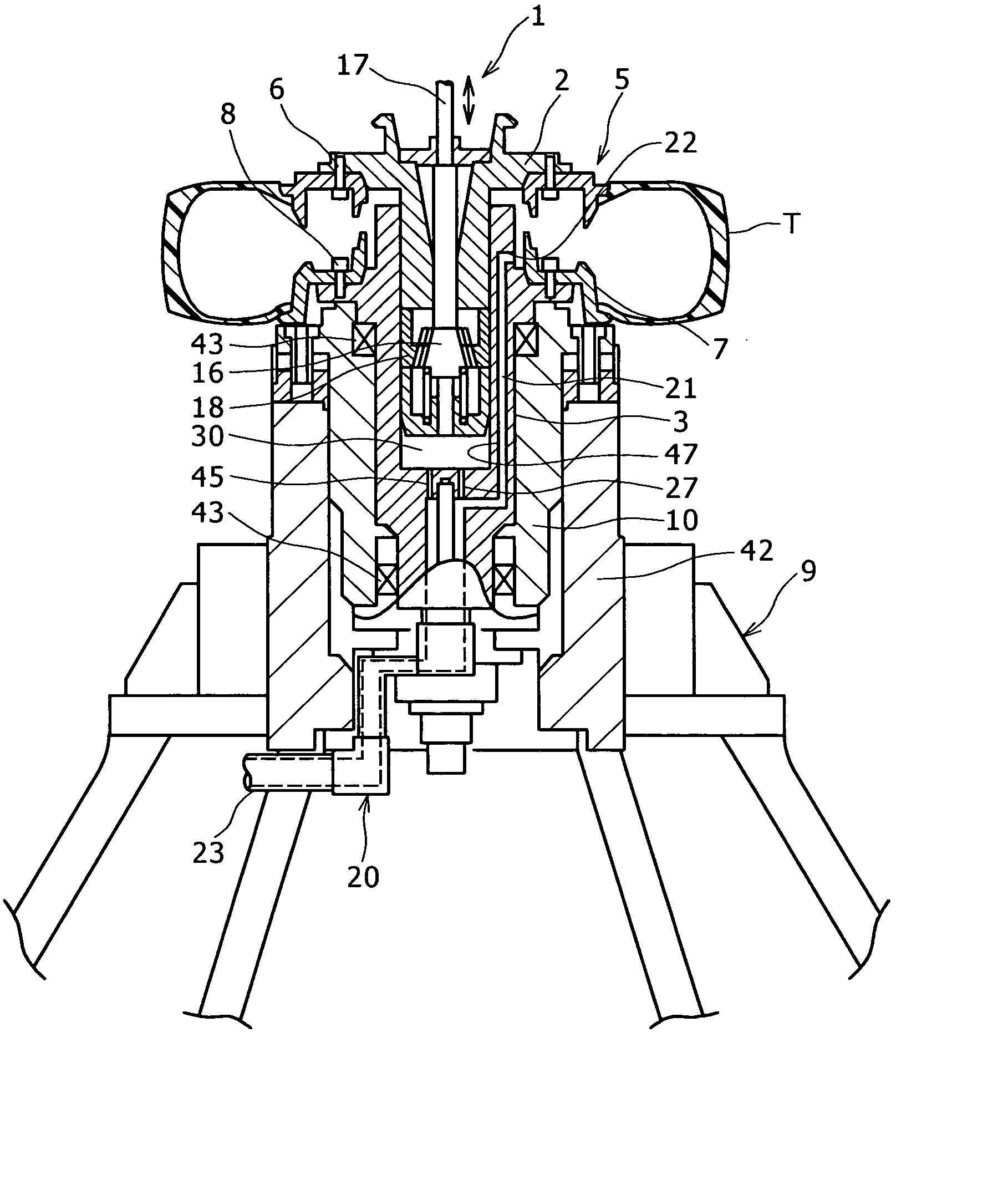
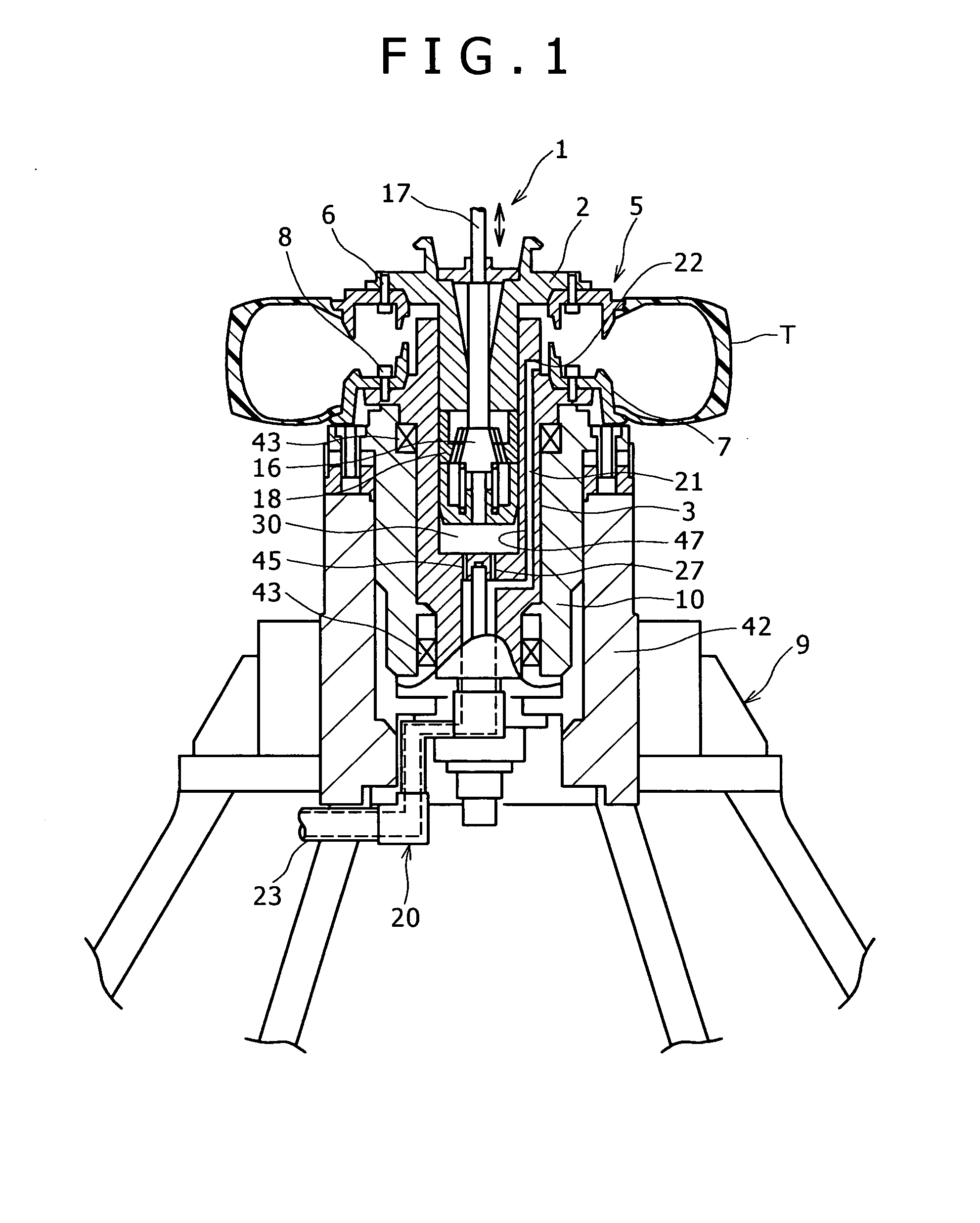
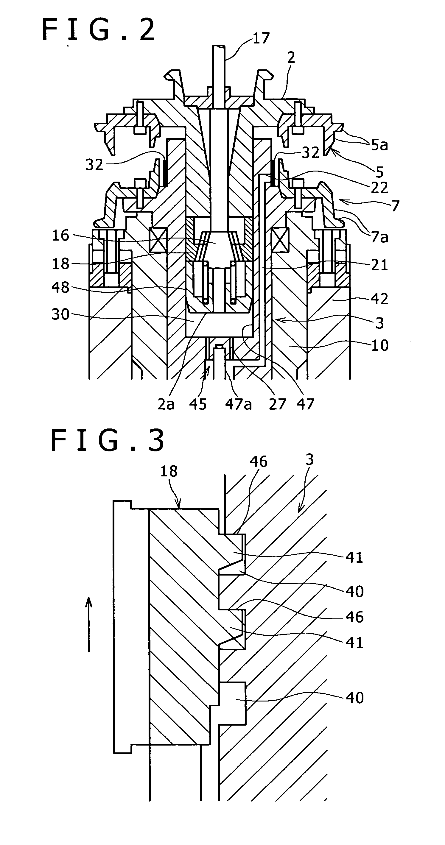
[0059] A description will now be given of a tire testing machine 1 according to the present invention with reference to FIGS. 1 to 4.

[0060] FIGS. 1 to 3 show the first embodiment of the tire testing machine 1 according to the present invention.

[0061] The tire testing machine 1 includes a tubular first spindle 3 whose one end opens largely, a second spindle 2 which has a columnar exterior, and is contained in the first spindle 3 thorough the opening, and a lock piece 18 which is engaged with the second spindle 2 so as to protrude from and retract into the second spindle 2 in the radial direction. The first spindle 3 and the second spindle 2 are vertically arranged, and relatively move, the first spindle 3 is designated as a lower spindle, and the second spindle 2 is designated as an upper spindle.

[0062] An upper rim 5 is fixed by means of bolts 6 to a bottom end portion of the upper spindle 2, and a lower rim 7 is fixed by means of bolts 8 to a top end portion of the lower spindle ...

second embodiment

[0115] A description will now be given of a tire testing machine 50 according to the present invention with reference to FIGS. 5 to 15.

[0116]FIG. 5 shows an overall front view of the tire testing machine 50, and FIG. 6 shows an overall side view of the tire testing machine 50. FIG. 7 shows a detailed view of a spindle device provided for the tire testing machine 50.

[0117] It should be noted that the left / right direction of the page is the left / right direction, and the direction passing trough the page is the front / rear direction in FIG. 5, and the left / right direction of the page is the front / rear direction, and the direction passing trough the page is the left / right direction in FIG. 6.

[0118] As shown in FIGS. 5 to 7, the tire testing machine 50 includes a main frame 51 and a spindle device 52 which is supported by the main frame 51, and detachably mounts the tire T. Moreover, the tire testing machine 50 includes a drum device 53 which applies a rotation and a load on the tire T ...

third embodiment

[0194] A description will now be given of a tire testing machine 110 according to the present invention with reference to FIGS. 16 to 20.

[0195]FIGS. 16 and 17 show an overall front view of the tire testing machine 110.

[0196] It should be noted that the left / right direction of the page is the left / right direction, and the direction passing trough the page is the front / rear direction in FIGS. 16 and 17.

[0197] The tire testing machine 110 includes a main frame 111 and a spindle device 112 which is supported by the main frame 111, and detachably mount the tire T.

[0198] Moreover, the tire testing machine 110 includes a drum device 113 which applies a rotation and a load on the tire T mounted on the spindle device 112.

[0199] The main frame 111 includes pillars 114 which are erected from an installation surface on front and rear, and left and right, connection bars 115 which connect top ends and bottom ends of the front and rear, and left and right pillars 114, and a mounting table 116...


PUM


Abstract

A spindle direction engaging device moves at least one of spindles in a mutually separating direction to closely engage a lock piece or a lock portion in a spindle direction of spindles while the lock piece is locked to the lock portion when a tire is not mounted. A second spindle includes a groove extending in a peripheral direction along an outer periphery thereof in sliding contact with the lock piece; sliding surfaces of the lock piece and the groove are receiving portions formed as flat surfaces to receive separating forces acting on both the spindles. A correction device corrects a gap between an inner ring of the spindle bearing and rolling elements of the spindle bearing, or a gap between an outer ring of the spindle bearing and the rolling elements of the spindle bearing, while the spindle is rotating. Preload bolts include a coolant passage formed by hollowing a corresponding portion passing a mounting hole of a detector, and a coolant can thus be supplied to the coolant passage.

Description

TECHNICAL FIELD [0001] The present invention relates to a technology of a tire testing machine used to measure tire uniformities. BACKGROUND ART [0002] A tire testing machine used to measure tire uniformities (static or dynamic characteristics of a tire) includes a spindle device which rotationally holds a tire while the tire is inflated at a predetermined internal pressure, and a drum device which applies a rotational force by bringing a drum in contact with an outer peripheral surface of the tire held by the spindle device (refer to patent document 1: Japanese Patent Laid-Open No. 2004-28700, or patent document 2: Japanese Utility Model Laid-Open No. H6-45239, for example). [0003] However, for this type of tire testing machine, it is not possible to avoid a load from being generated in the tire testing machine itself due to a tire being held in an inflated state, or being rotated while the tire uniformities are being measured, and the load causes a reduction of test accuracy. [000...

Claims


Application Information

Patent Timeline
Patent Type & Authority Applications(United States)
IPC IPC(8): G01M17/013G01M1/16B60C19/00G01M1/04G01M1/34G01M17/02
CPCG01M17/021G01M1/045G01M1/04G01M1/16G01M17/02
Inventor SHINOMOTO, YOSHIYUKIKATO, MIKIONONAKA, TOSHIKATSU
Owner KOBE STEEL LTD
Why Eureka
Try Eureka