
Turbine blade

a turbine blade and turbine blade technology, applied in the field of turbine blades, can solve the problems of severe impairment, disadvantage, and adverse effect of steam turbine efficiency, and achieve the effect of improving inflow and radial reaction distribution

Inactive Publication Date: 2010-09-14
SIEMENS ENERGY GLOBAL GMBH & CO KG
View PDF19 Cites 9 Cited by
  • Summary
  • Abstract
  • Description
  • Claims
  • Application Information

AI Technical Summary

Benefits of technology

The present invention aims to improve the efficiency of a turbine blade and turbomachine. This is achieved through the use of specific features described in the claims, which enhance the distribution of radial reaction and improve the inflow. These improvements lead to improved performance and efficiency of the turbine.

Problems solved by technology

The flow of a flow medium in the last stage of a low-pressure turbine having a large inflow cross section leads, in the case of a high blade length to hub ratio, to a radial reaction distribution which has an adverse effect on the efficiency of the steam turbine.
The reaction distribution is in this case different in the radial direction and is low at the hub and high at the casing, this being felt to be a disadvantage.
A low or even negative reaction of the hub leads to severe impairments and to efficiency losses of the turbine during operation.
The high attack velocity has an adverse effect on efficiency, since the behavior of flow losses is squarely proportional to velocity.

Method used


Image

  • Turbine blade
  • Turbine blade
  • Turbine blade

Examples


Embodiment Construction

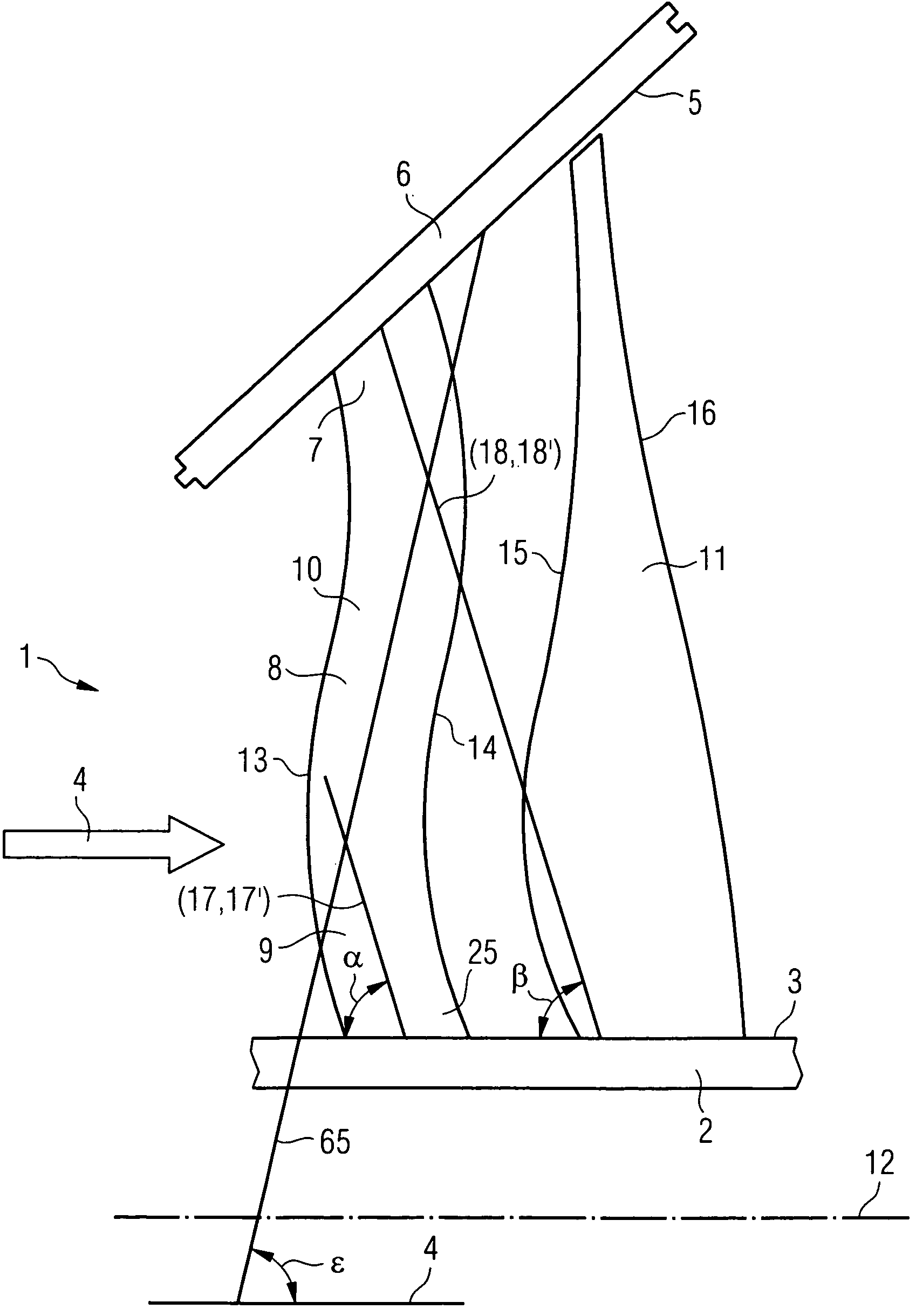
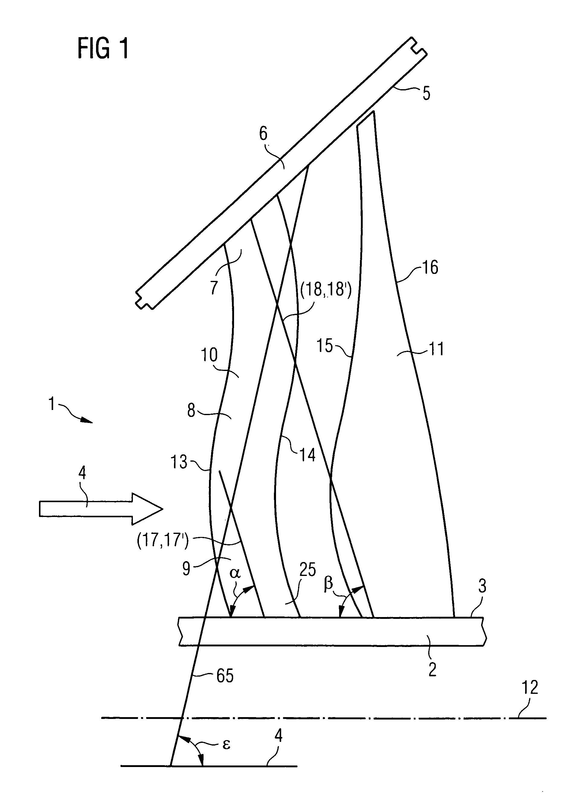
[0025]In the steam turbine final stage shown diagrammatically in a side view in FIG. 1, the walls delimiting a throughflow duct 1 are, on the one hand, a rotor-side duct wall 3 and, on the other hand, a stator-side duct wall 5. The stator-side duct wall 5 belongs to an inner casing 6. A final stage consists of a row of guide blades and a row of moving blades, of which in each case only one guide blade 10 and one moving blade 11 is shown in FIG. 1 for the sake of clarity. The guide blades are fastened to the inner casing 6 in a way not illustrated.

[0026]The moving blades are fastened in the rotor 2 in a way not illustrated.

[0027]The guide blade 10 has a stator-side end 7, a middle region 8 and a rotor-side end 9. A flow medium can flow through the duct 1 in the direction of flow 4. The direction of flow 4 is essentially parallel to an axis of rotation 12 of the rotor 2. The guide blade 10 has a leading edge 13 and a trailing edge 14 which are formed over the entire blade height.

[0028...


PUM


Abstract

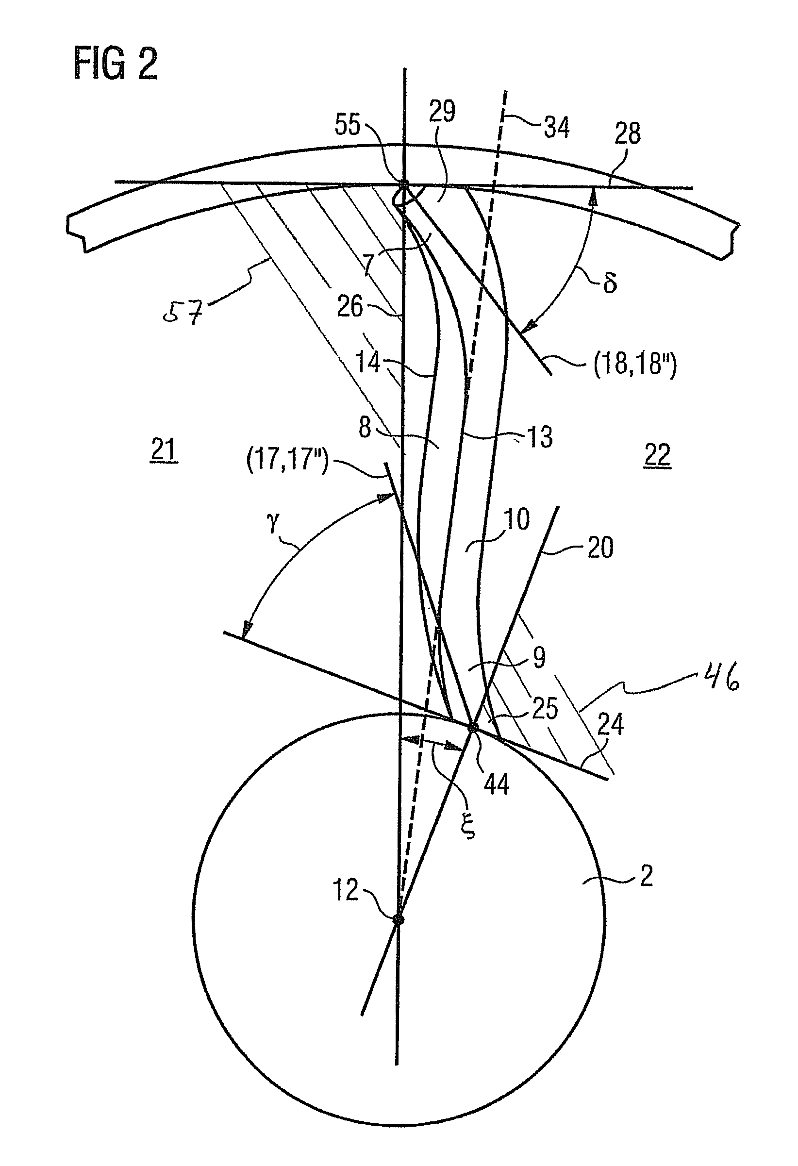
A turbine blade is provided, comprising a stator-side end located toward a stationary stator cylinder of the turbine, a rotor-side end located toward an axial rotor of the turbine, a leading edge located between the stator-side end and the rotor-side end, a trailing edge located between the stator-side end and the rotor-side end and located down-stream of the leading edge with respect to a fluid flow direction, wherein the rotor-side and stator-side ends have a negative sweep angle as measured between the instantaneous tangent of the blade surface and the fluid flow direction. Also, a turbine blade is provided, comprising a stator-side end located toward a stationary stator cylinder of the turbine, a rotor-side end located toward an axial rotor of the turbine, a delivery side located between the stator-side end and the rotor-side end, a suction side located between the stator-side end and the rotor-side end and located down-stream of the leading edge with respect to a fluid flow direction, wherein the rotor-side end is inclined toward the delivery side and the stator-side end is inclined with respect to a fluid flow direction.

Description

CROSS REFERENCE TO RELATED APPLICATIONS[0001]This application is the US National Stage of International Application No. PCT / EP2004 / 006624, filed Jun. 18, 2004 and claims the benefit thereof. The International Application claims the benefits of European Patent application No. 03015496.7 EP filed Jul. 9, 2003, all of the applications are incorporated by reference herein in their entirety.FIELD OF THE INVENTION[0002]The invention relates to a turbine blade which has a blade height, a rotor-side end and a stator-side end, a leading edge and trailing edge and a suction side and delivery side and which is designed for use in relation to a general direction of flow, and also to a turbomachine which is equipped with such a turbine blade.BACKGROUND OF THE INVENTION[0003]In steam turbine construction, for example, curved guide blades are used as an embodiment of turbine blades especially when high three-dimensional flows occur which exhibit pronounced radial differences in the static pressure...

Claims


Application Information

Patent Timeline
Patent Type & Authority Patents(United States)
IPC IPC(8): F01D9/04F01D5/14
CPCF01D5/141F01D5/142Y02T50/673Y02T50/60Y10S416/02
Inventor BORTHWICK, DONALDCHEN, SHUNSTUER, HEINRICHTRUCKENMULLER, FRANK
Owner SIEMENS ENERGY GLOBAL GMBH & CO KG
Learn More