
Sample processing apparatus and method using vacuum chamber

a vacuum chamber and processing apparatus technology, applied in laboratory glassware, multi-stage water/sewage treatment, separation processes, etc., can solve the problems of difficult to incorporate the bio sample processing apparatus to have multiple channels, difficult to fabricate the micro pump, and relatively complicated structur

Inactive Publication Date: 2010-09-14
SAMSUNG ELECTRONICS CO LTD
View PDF11 Cites 0 Cited by
  • Summary
  • Abstract
  • Description
  • Claims
  • Application Information

AI Technical Summary

Benefits of technology

The present invention provides a bio sample processing apparatus using vacuum chambers that can process a bio sample without an external energy source. The apparatus includes a bio processor for pre-processing the bio sample, a first vacuum chamber, and a second vacuum chamber. The bio sample is injected into the first vacuum chamber and then moved to the second vacuum chamber due to a pressure difference between the chambers. The apparatus can be used to acquire the bio sample by using a micro-sized needle. The technical effect of this invention is to provide a convenient and efficient method for processing bio samples without the need for external energy sources.

Problems solved by technology

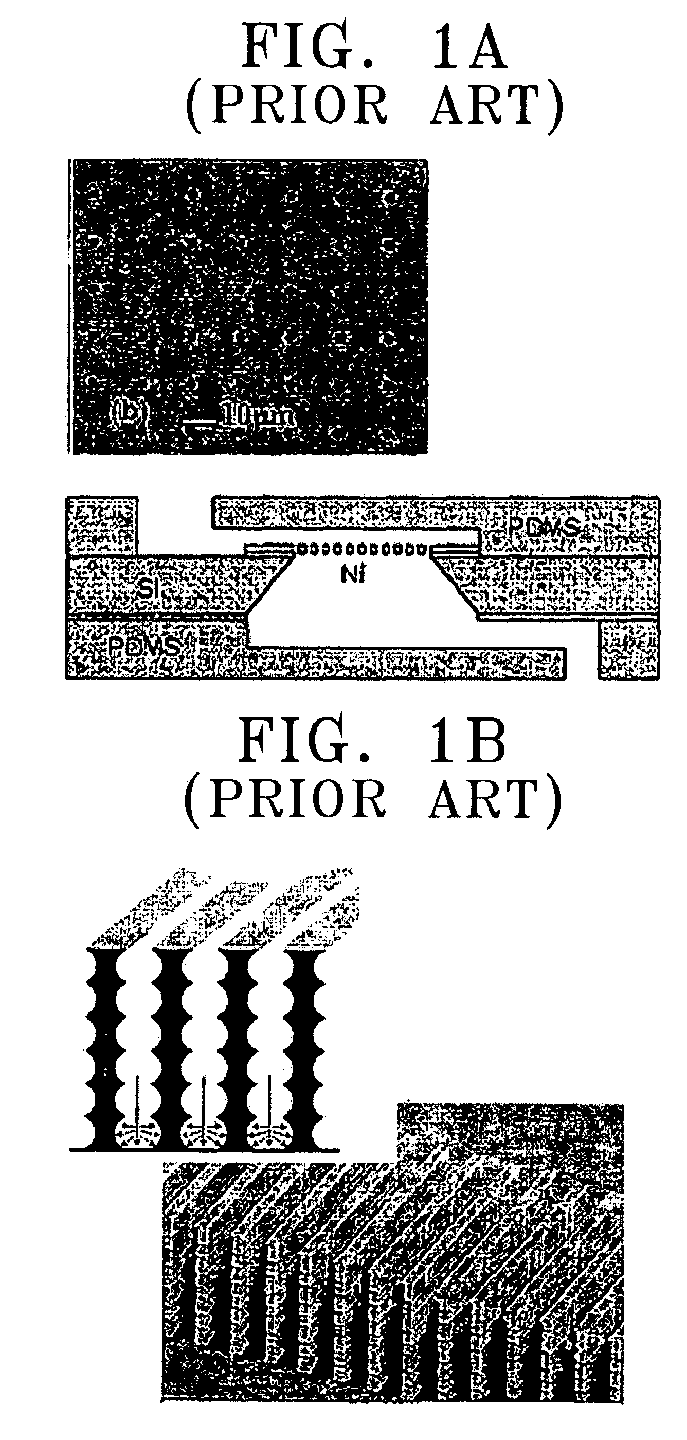
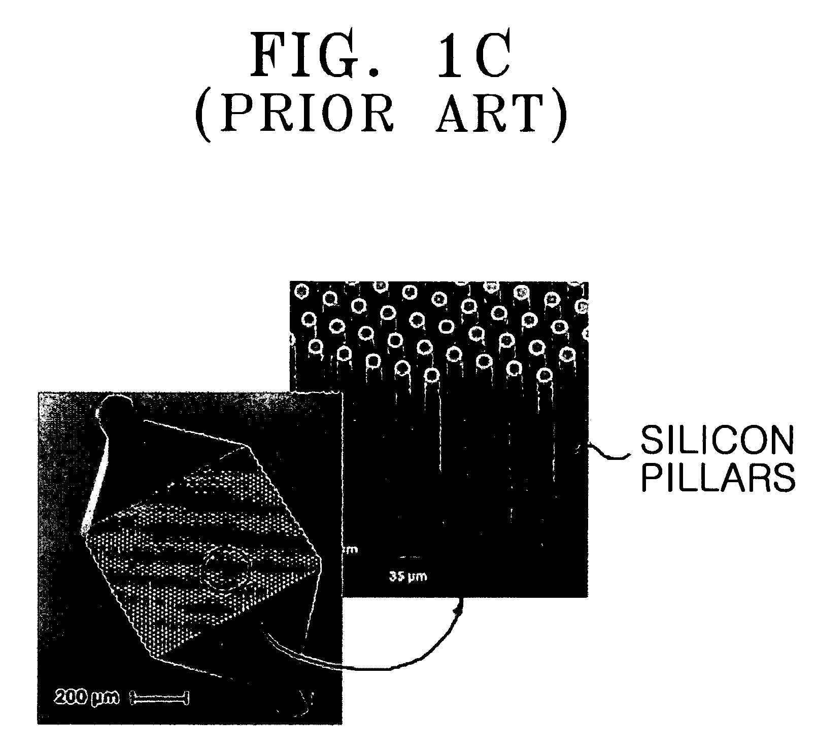
Because the bio sample processing apparatus is not for one time use, a cleaning process is necessary and it is hard to embody the bio sample processing apparatus to have multiple channels.
Therefore, it includes a micro electromechanical (MEMS) pump inside, which makes the structure relatively complicated.
When the micro pump is used, there are problems in that the process for fabricating the micro pump is quite complicated, and that the production cost is increased.
In addition, the micro pump has relatively weak performance, compared to other pumps.
However, when an external pump is used, it is hard to connect and control the microstructure and the external pump.

Method used


Image

  • Sample processing apparatus and method using vacuum chamber
  • Sample processing apparatus and method using vacuum chamber
  • Sample processing apparatus and method using vacuum chamber

Examples


Embodiment Construction

[0031]Certain exemplary embodiments of the present invention will be described in greater detail with reference to the accompanying drawings.

[0032]In the following description, the same drawing reference numerals are used for the same elements even in different drawings. Matters described here, such as construction details and elements, are those which assist in a comprehensive understanding of the invention. It will be appreciated that the present invention can be carried out without describing well-known functions or constructions in detail.

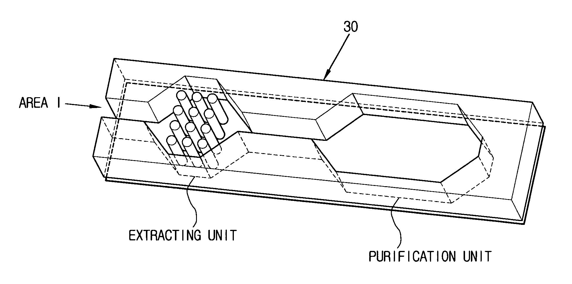
[0033]FIGS. 3A to 3D are diagrams of a bio sample processing apparatus using vacuum chambers consistent with an exemplary embodiment of the present invention. FIG. 3A is a perspective diagram showing the bio sample processing apparatus using vacuum chambers consistent with a first exemplary embodiment of the present invention. FIG. 3B is an exploded perspective diagram illustrating the bio sample processing apparatus of FIG. 3A. FIG. 3C is a cr...


PUM

PropertyMeasurementUnit
pressureaaaaaaaaaa
Pressureaaaaaaaaaa
vacuumaaaaaaaaaa

Abstract

A bio sample processing apparatus and method using vacuum chambers in which a bio sample is injected into a first vacuum chamber connected with one end of a bio processor and, after processing, is ejected into a second vacuum chamber connected with the other end of the bio processor. The vacuum chambers and bio processor are connected with each other to form an environment with a pressure lower than atmospheric pressure, and the bio sample moves toward the second vacuum chamber due to the pressure difference created by the injection of the bio sample into the first vacuum chamber.

Description

CROSS-REFERENCE TO RELATED APPLICATIONS[0001]This application claims the benefit under 35 U.S.C. §119 (a) from Korean Patent Application No. 2004-57898 filed on Jul. 24, 2004 in the Korean Intellectual Property Office, the disclosure of which is incorporated in its entirety herein by reference.BACKGROUND OF THE INVENTION[0002]1. Field of the Invention[0003]Apparatuses consistent with the present invention relate generally to bio sample processing. More particularly, the present invention relates to a bio sample processing apparatus and method in which low-pressure vacuum chambers are set up in both ends of a bio processor and a bio sample is made to pass through the bio processor due to a pressure difference.[0004]2. Description of the Related Art[0005]A biochip is a biological micro chip that can analyze gene expression, the way of distribution, and mutation by arraying and immobilizing hundreds to hundreds of thousands of biomolecules such as deoxyribonucleic acid (DNA), DNA fragm...

Claims


Application Information

Patent Timeline
Patent Type & Authority Patents(United States)
IPC IPC(8): C12M1/34C02F9/00C12M3/00
CPCB01L3/502715B01L3/50273B01L2200/10B01L2300/049B01L2400/049B01L2400/06B01L9/527G01N1/286G01N2035/00158
Inventor PARK, TAE-SIKLEE, SUNG-HEEKANG, JUNG-HOKIM, YOUNG-ILLEE, MOON-CHUL
Owner SAMSUNG ELECTRONICS CO LTD
Learn More