Biosorption wastewatertreatment system

a wastewater treatment system and biosorption technology, applied in water/sludge/sewage treatment, water treatment parameter control, specific water treatment objectives, etc., can solve the problems of low wastewater treatment degree and low reliability of biosorbers, and achieve the effect of controlling the amount of coagulant and preventing water from entering the air compressor

Inactive Publication Date: 2018-10-25
PUKEMO MIKHAIL
View PDF0 Cites 0 Cited by
  • Summary
  • Abstract
  • Description
  • Claims
  • Application Information

AI Technical Summary

Benefits of technology

[0015]In another embodiment of the present invention, the biosorber automated control module is connected to a dosing pump. Therefore, it is possible to control the metering pump, and periodically turn it on and off, thus regulate the level of effluent in the bioreactor.
[0016]In another embodiment of the present invention, the biosorber automated control module is connected to an air compressor of a system for saturating water with air / oxygen. Therefore, it is possible to control the operation of an air compressor of the system of water saturation with air oxygen.
[0017]In another embodiment of the present invention, the biosorber automated control module is connected to a dispenser for the coagulant. Therefore, it is possible to control the amount of coagulant that is added to the effluent.
[0018]In another embodiment of the present invention, the air compressor has a check valve to prevent water from entering. Therefore, it is possible to prevent water from entering the air compressor.

Problems solved by technology

One of the shortcoming of the prior art that use a bioreactor is that they have a low degree of wastewater treatment, as well as low reliability of the biosorber.
This is due to the fact that active coal (sorbent), is subject to colmatage (i.e., blockage, clogging, natural carburizing), and the active coal (sorbent), may wash out of the bioreactor chamber.

Method used


Image

  • Biosorption wastewatertreatment system
  • Biosorption wastewatertreatment system
  • Biosorption wastewatertreatment system

Examples


Embodiment Construction

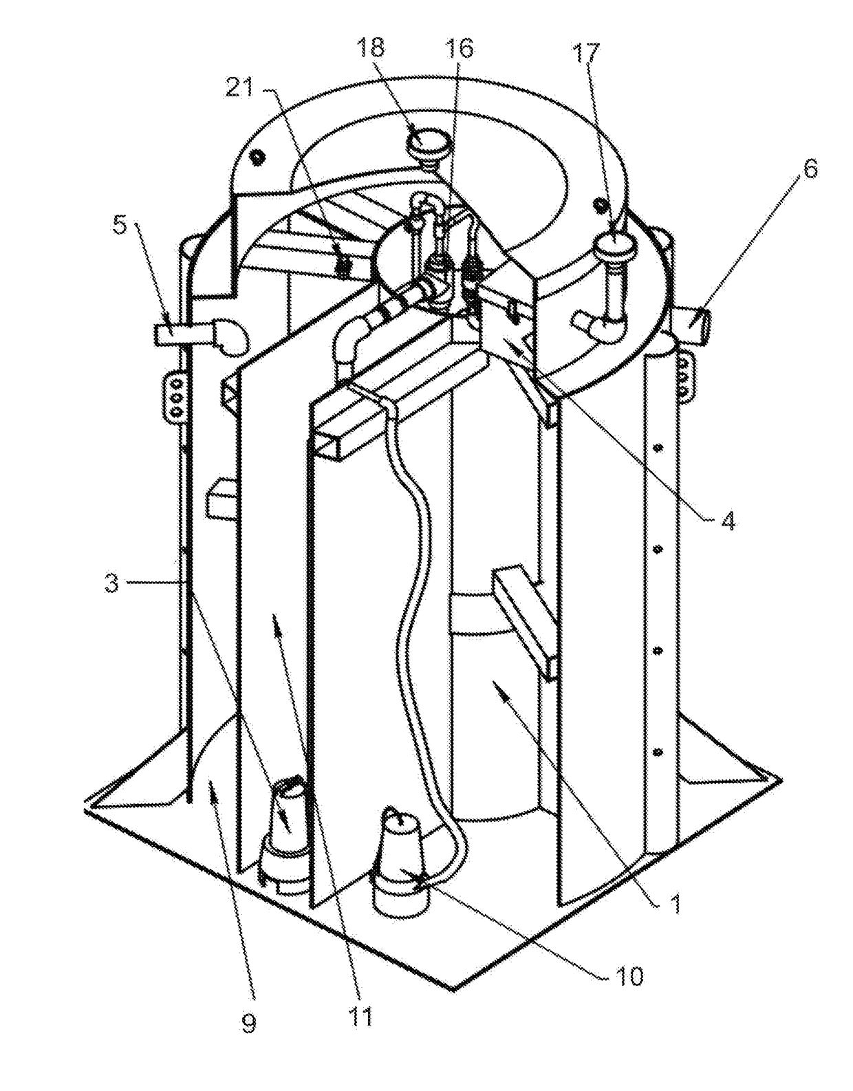
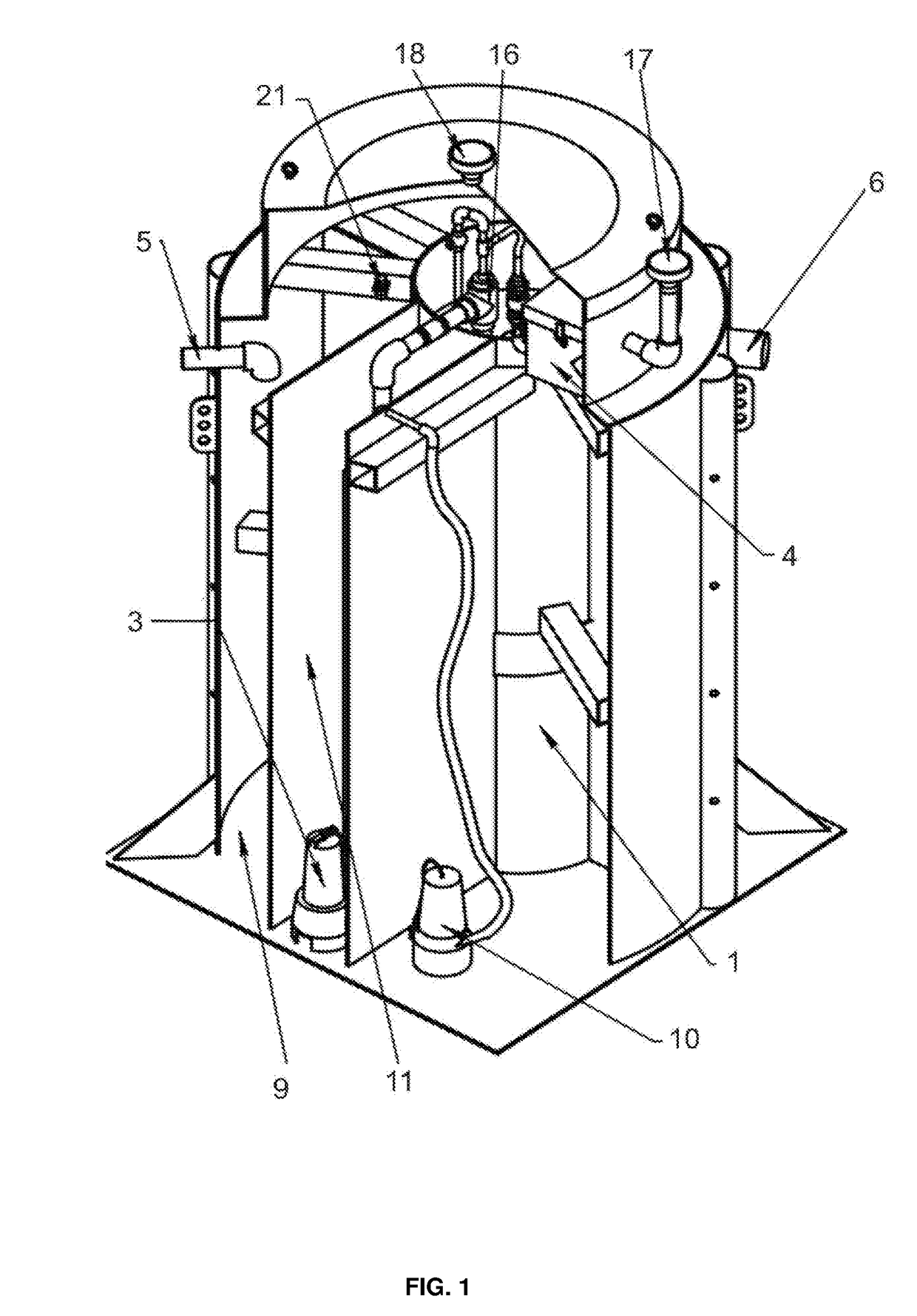
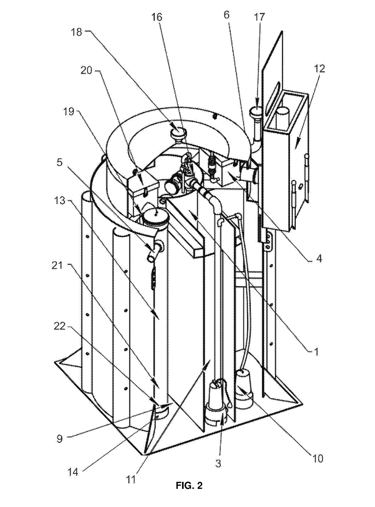
[0027]The technology disclosed herein, in accordance with one or more various embodiments, is described in detail with reference to the following figures. The drawings are provided for purposes of illustration only and merely depict typical or example embodiments of the disclosed technology. These drawings are provided to facilitate the reader's understanding of the disclosed technology and shall not be considered limiting of the breadth, scope, or applicability thereof. It should be noted that for clarity and ease of illustration these drawings are not necessarily made to scale.

[0028]According to FIGS. 1 to 3, the wastewater biosorber comprises of a bioreactor 1 with a fluidized bed of charge (sorbent) 2, a system for saturating the water with air oxygen comprising a pump of the system for saturating the water with air / oxygen 3, a compressor of the system for saturating the water with air oxygen 4, a sewage pipeline 5 for treatment, a purified water outlet line 6 and a recirculated...


PUM

PropertyMeasurementUnit
stabilityaaaaaaaaaa
volatilityaaaaaaaaaa
concentrationaaaaaaaaaa

Abstract

The invention relates to wastewater treatment systems, in particular to biosorbers for wastewater treatment, comprising a bioreactor with a fluidized bed of charge and a layer of filtering charge, a system for saturating the water with air oxygen, a sewage treatment pipeline, a purified water discharge line and a recirculated flow line with a circulating Pump. According to the invention, the biosorber includes a receiving and dispensing chamber connected via a metering pump to the chamber with a coal removal trap that is connected to the fluidized bed bioreactor through a circulation pump, the biosorber including an automated biosorber control module, the bioreactor being provided with a convex reflector Active coal, installed in the upper part of the bioreactor, designed to provide laminar upward movement of liquid along the walls of the bioreactor. The technical result achieved is to increase the degree of wastewater treatment while ensuring high reliability of operation.

Description

FIELD OF THE INVENTION[0001]The present invention relates in general to wastewater treatment systems, and in particular to a biosorption wastewater treatment system.BACKGROUND OF THE INVENTION[0002]Treatment and purification of wastewater is regularly utilized in industrial and domestic wastewaters. In particular, with ever increasing water shortage, proper handling of domestic and industrial wastewater has become more important. In addition, discharge of wastewater in rivers and lakes requires a prior treatment to remove hazardous materials. Various treatment systems are used to decontaminate the wastewater. One important stage of wastewater treatment is biological oxidation. Powdered activate carbons / coal (sorbents) are commonly used to adsorb and remove biologically inhibitory organic compounds. Other types of sorbents are natural and synthetic zeolites, and ion exchangers.[0003]One of the shortcoming of the prior art that use a bioreactor is that they have a low degree of wastew...

Claims


Application Information

Patent Timeline
Patent Type & Authority Applications(United States)
IPC IPC(8): C02F3/12C02F3/08C02F3/00C02F3/02
CPCC02F3/1226C02F3/085C02F3/006C02F3/02C02F2301/046C02F2303/16C02F2101/10C02F2101/30C02F3/1215C02F1/52C02F3/106C02F2209/008C02F2209/42Y02W10/10Y02W10/30
Inventor PUKEMO, MIKHAIL
Owner PUKEMO MIKHAIL
Why Eureka
Try Eureka