
Crush resistant conductor insulation

a conductor and resistance technology, applied in the direction of insulated conductors, cables, conductors, etc., can solve the problems of increasing cable weight and cable size, and achieve the effect of increasing impedance, increasing impedance per lb/1000, and increasing impedan

Inactive Publication Date: 2010-09-14
THE CHEMOURS CO FC LLC
View PDF23 Cites 19 Cited by
  • Summary
  • Abstract
  • Description
  • Claims
  • Application Information

AI Technical Summary

Benefits of technology

The present invention provides a process for twisting a pair of polymer-insulated conductors to form a twisted pair with improved impedance efficiency compared to polymer insulation of the same weight but of uniform thickness. The twisting involves extruding polymer onto the conductors to create a cylindrical exterior surface with peaks and valleys. The peaks and valleys are caused by the extruding process and backtwisting the conductors in opposite directions. The twisting and backtwisting cause the peaks to align with the valleys, resulting in a nested relationship between the peaks and valleys. The process can be carried out using a commercial twinning machine and a polymer jacket can be applied to encase the twisted pair of conductors to form a cable. The cable has improved impedance efficiency and requires less polymer insulation to achieve the same impedance as with conventional polymer insulation.

Problems solved by technology

The problem with increasing the amount of polymer insulation used is that there is an increase in cable weight and cable size.

Method used


Image

  • Crush resistant conductor insulation
  • Crush resistant conductor insulation
  • Crush resistant conductor insulation

Examples


example 1

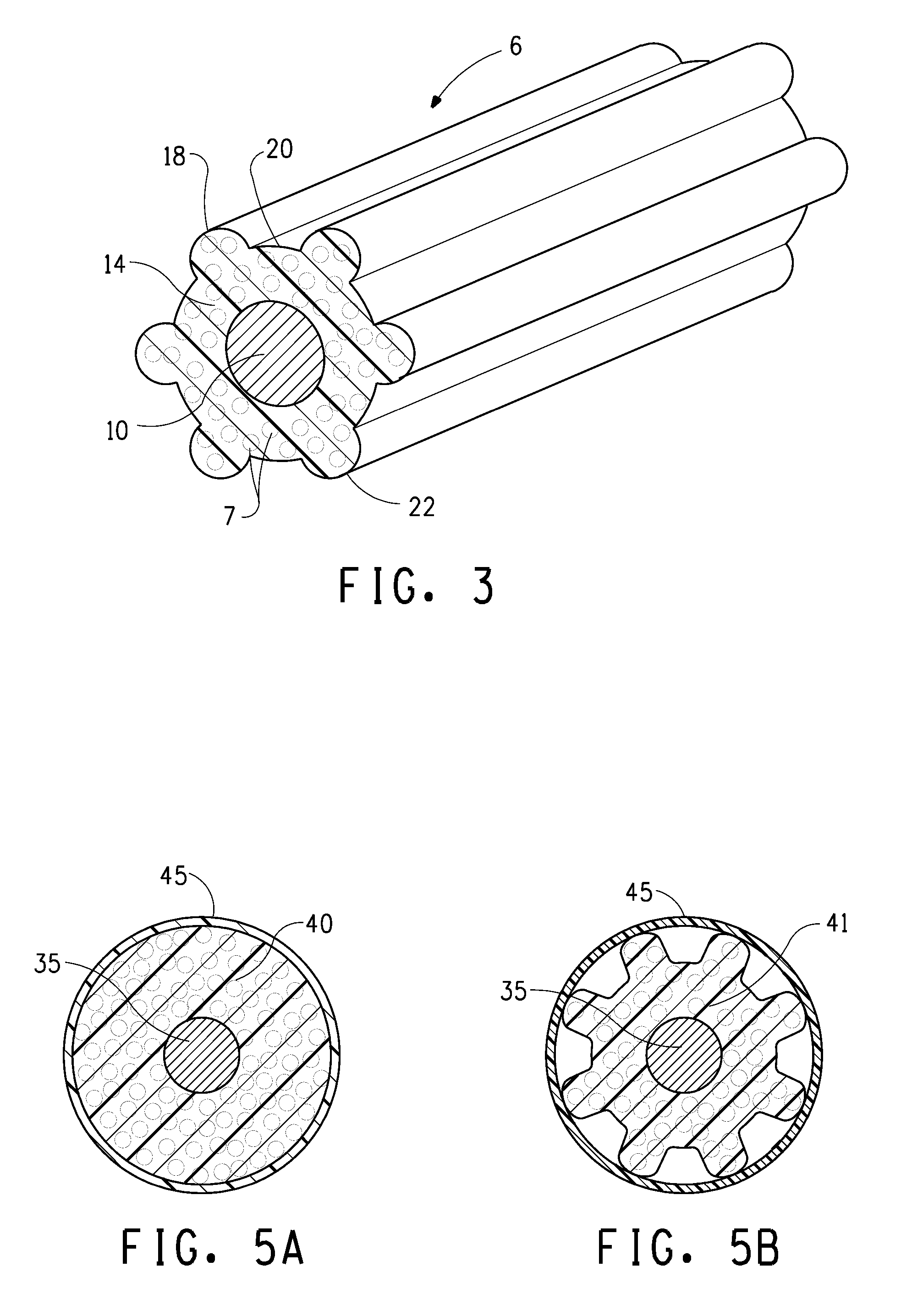
[0050]In an embodiment of the present invention, the profile of a scalloped insulation surface is used for a foamed insulation coaxial cable as shown in FIG. 5B. In Table 1 below, the properties of a typical or conventional foamed coaxial cable (FIG. 5A) are compared to the scalloped foamed insulation coaxial cable (FIG. 5B) of the present invention. As indicated in Table 1 the significant difference is the insulation weight. Capacitance, VP (velocity of propagation) and calculated impedance are virtually the same. The weight of the conventional foamed insulation is about 0.918 lb / 1000 ft versus the reduced weight of 0.721 lb / 1000 ft. This weight reduction in material while maintaining the electrical and mechanical properties of the coaxial cable provides a significant cost savings to the manufacturer.

[0051]Table 1 shows the electrical properties of the conventional foamed coaxial cable (FIG. 5A) in comparison to the present invention of the scalloped foamed coaxial cable (FIG. 5B)....

example 2

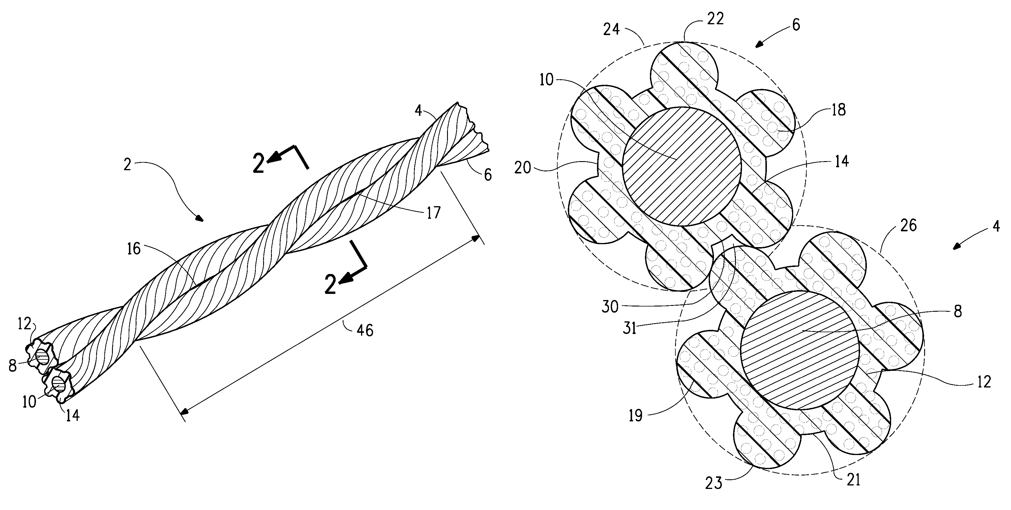
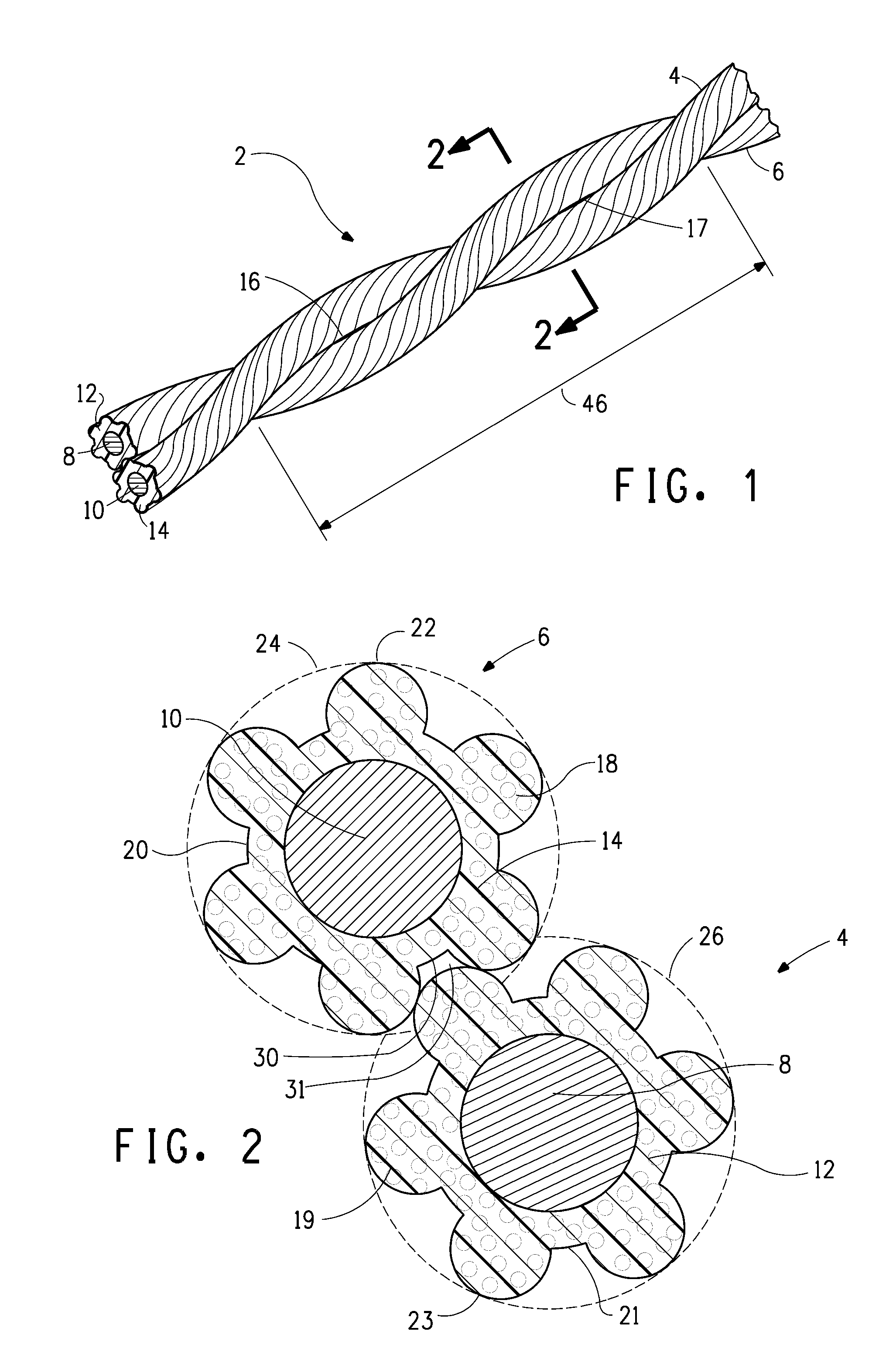
[0058]This Example compares the impedance for twisted pairs of insulated wires when (i) the insulation for the twisted pair is a profile insulation of the present invention (Invention in Table 2) and (ii) the insulation for the twisted pairs is non-profile insulation, i.e. resembling a cylinder around the wire (Conventional in Table 2), wherein the weight of the insulation for all of the twisted pairs is kept constant at 0.832 lb / 1000 ft. The impedance results are shown in Table 2 for various twinning rates (twists / min) and lays. The lay for the twisted pair is defined as the inches per complete twist, such as is shown by the bracket 46 in FIG. 1 The conventional insulation has a thickness of 9 mils. The Invention insulation has the cross-sectional configuration shown in FIG. 8. Details of this configuration are given in Example 4. The nesting of the insulated conductors forming the twisted pair of the Invention in Table 2 is obtained by backtwisting 30% each insulated conductor in ...

example 3

[0061]The present invention also shows a reduction in polymer insulation required for foam designs when compared to the standard polymer insulation under similar conditions. The foamed polymer insulation of this Example resembles that of FIG. 2, wherein the 6 peaks are each 4 mils (0.1 mm) wide and 4 mils (0.1 mm) high and the overall insulation thickness is 11 mils (0.28 mm). The thickness of the insulation at the inner circumference defined by he valleys is 8 mils (0.2 mm). The diameter of the insulation from peak top to peak top is about 45 mils (1.143 mm). The peaks occupy about 41 % of the inner circumference of the polymer insulation defined by the valleys.

[0062]When this polymer-insulated conductor is twinned with another of the same polymer-insulated conductors at a twinning rate of 2000 turns / min to form a lay of 0.3 in (7.6 mm) for the twisted pair, a peak of one insulation nests in a valley of the other insulation assisted by the back-twisting of the individual polymer-in...


PUM

PropertyMeasurementUnit
thicknessaaaaaaaaaa
thicknessaaaaaaaaaa
impedanceaaaaaaaaaa

Abstract

A process of twinning a pair of polymer-insulated conductors to form a twisted pair, where the polymer-insulated conductors are formed by extruding a uniformly thick coating of polymer onto the conductors. More than one twisted pair is encased in a polymer jacket forming a cable. The twisted pair obtains a desirable average impedance performance using a reduced amount by weight of polymer forming said polymer-insulated conductors by: (i) extruding to form longitudinally running peaks and valleys in the exterior surface of each of the polymer-insulated conductors of the pair of polymer-insulated conductors and (ii) twinning resultant polymer-insulated conductors to nest at least one of the peaks in the exterior surface of one of the polymer-insulated conductors in at least one of said valleys in the exterior surface of the other of the polymer-insulated conductors of the pair of polymer-insulated conductors.

Description

FIELD OF THE INVENTION[0001]The present invention relates to a crush resistant conductor insulation. More particularly, the present invention relates to a crush resistant polymer insulated conductor twinning process or cable where the polymer insulation is foamed or unfoamed, has peaks and valleys, and maintains the electrical and mechanical properties of a typical cylindrical polymer insulated conductor.BACKGROUND OF THE INVENTION[0002]Twisted pair communications cable is used for high frequency signal transmission, typically in plenum areas of buildings. The cable is composed of typically multiple twisted pairs of polymer-insulated conductors, covered by a polymer jacket. In twisted pair data cables, the individual insulated conductors are typically twisted into pairs, and four pairs are cabled together and jacketed to make the cable. Each pair is twisted at a different lay (conventionally measured in inches / turn) to reduce electrical coupling between adjacent twisted pairs (i.e. ...

Claims


Application Information

Patent Timeline
Patent Type & Authority Patents(United States)
IPC IPC(8): H01B7/00
CPCH01B7/0275H01B7/0233Y10T29/49194Y10T29/49117Y10T29/4913Y10T29/49121Y10T29/49165Y10T29/49128
Inventor THUOT, GARYYOUNG, ROBERT THOMASNETTA, JOHN L.
Owner THE CHEMOURS CO FC LLC
Learn More