Multi-level signaling

a signaling and multi-level technology, applied in the direction of pulse technique, process and machine control, instruments, etc., can solve the problems of overlapping of the switching phase between the controller and the driver circuit, and the allocation of a pair of pins, so as to minimize or prevent the overlap of the switching phas

Active Publication Date: 2010-09-14
INFINEON TECH AMERICAS CORP
View PDF9 Cites 11 Cited by
  • Summary
  • Abstract
  • Description
  • Claims
  • Application Information

AI Technical Summary

Benefits of technology

[0017]Embodiments herein are novel and useful over conventional tri-state signaling. For example, toggling of the multi-state signal within a range such as above and below a first threshold value enables the driver to reproduce a pulse width modulation for alternating between activating a high side switch circuitry and low side switch circuitry of a respective power converter phase. When the multi-state signal moves outside of the range such as above the second threshold value, the driver circuit deactivates both the high side switch circuitry and the low side switch circuitry of the respective power converter phase. Such a configuration enables a smooth transition between control states. For example, enabling of the switch circuit in the multi-state signal coincides with the switching of the multi-state signal above and below the first threshold value within the range. When outside of the range, both the high side switch circuitry and low side switch circuitry are deactivated.
[0018]Thus, a multi-state signal (e.g., a voltage control signal or a current control signal) according to embodiments herein can smoothly transition from a first state (causing activation of low side switch circuitry and deactivation of high side switch circuitry) through a second state (causing activation of high side switch circuitry and deactivation of low side switch circuitry) to a third state (causing deactivation of both the low side switch circuitry and the high side switch circuitry).

Problems solved by technology

Allocation of a pair of pins (one for the pulse width modulation signal and an enable signal) on both a controller and driver circuit for each power converter phase can be quite costly when a power supply includes many phases.

Method used


Image

  • Multi-level signaling
  • Multi-level signaling
  • Multi-level signaling

Examples


Embodiment Construction

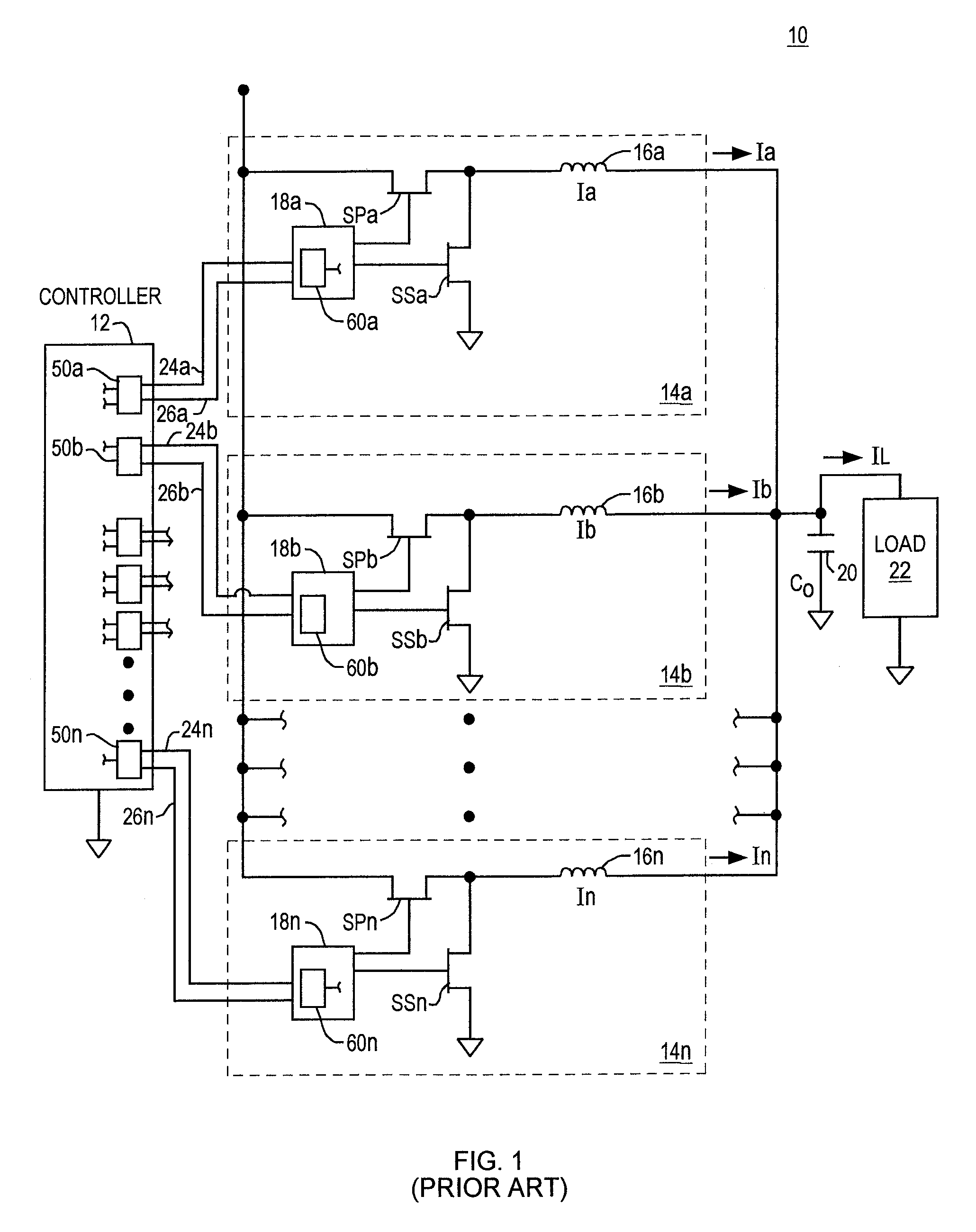
[0035]FIG. 1 shows a simplified schematic diagram of a prior art multiphase power converter 10 according to conventional methods. In the figure a digital controller 12 sends a pair of channels (e.g., channel pairs 24a, 26a; 24b, 26b; 24n, 26n) to each of a plurality of switching power converter phases 14a, 14b . . . 14n.

[0036]Channels 24a, 24b . . . 24n carry binary enable / disable control signals; channels 26a, 26b . . . 26n carry switch control signals that indicate the desired states of one or more of the switches in the converter.

[0037]Each buck switching power converter phase 14a, 14b . . . 14n comprises a phase switch controller 18a, 18b . . . 18n, a power switch SPa, SPb . . . SPn, a synchronous switch SSa, SSb . . . SSn, and an inductor 16a, 16b . . . 16n. Enable / disable control and switch control signals are generated by drivers 50a, 50b, 50n (which may be part of controller 12, as illustrated in FIG. 1, or which may be external to the controller) and are detected and decod...


PUM


Abstract

A control circuit generates an output based on the first signal and the second signal by encoding the output to be a multi-state signal having at least three states. A magnitude of the multi-state signal generated by the controller varies depending on binary states of the first signal and the second signal. The controller utilizes the output (i.e., the multi-state signal) to control a switching circuit. A driver circuit receives the output generated by the control circuit. In one embodiment, the multi-state signal has more than two different logic states. The driver decodes the multi-state signal for generating signals to control switches in the switching circuit. One signal generated by the driver circuit is a pulse width modulation signal; another signal generated by the driver circuit is an enable / disable signal.

Description

BACKGROUND[0001]Conventional binary signaling includes sending information by means of two distinguishable states (e.g., 1 and 0). Conventional ways of transferring multi-state information (e.g., information that has more than two distinguishable states) over a single channel (e.g., a single wire plus a return) requires some form of multi-state encoding.[0002]One conventional way to send multi-state information over a single signal channel is to encode the multi-state digital data into packets of bits and send the packets using binary serial signaling.[0003]Another conventional way to send multi-state information over single signal channel is to associate different signal amplitudes with different states. In one example, a “ternary” or “three-state” communication scheme comprises a sending unit to encode a sequence of three distinguishable digital states into a signal comprising three distinct signal amplitudes and a receiving unit that receives and decodes the signal levels to reco...

Claims


Application Information

Patent Timeline
Patent Type & Authority Patents(United States)
IPC IPC(8): H03K19/00G05F1/00
CPCH02M3/1584H03K19/0002H03K19/09425H02M2001/0012H02M1/0012
Inventor CANDAGE, ANTHONY B.POLHEMUS, GARY D.JASA, HRVOJECARROLL, ROBERT T.
Owner INFINEON TECH AMERICAS CORP
Why Eureka
Try Eureka