Magnetic field generator for MRI

a magnetic field and generator technology, applied in the direction of magnets, magnet bodies, instruments, etc., can solve the problems of reducing the magnetic field intensity, construction may not be able to hold permanent magnets, and the permanent magnet group may not be able to achieve the effect of reducing the size of the construction, facilitating manufacturing, and simple shap

Active Publication Date: 2010-09-14
HITACHI METALS LTD
View PDF45 Cites 58 Cited by
  • Summary
  • Abstract
  • Description
  • Claims
  • Application Information

AI Technical Summary

Benefits of technology

[0008]According to the technique disclosed in JP Patent No. 2699250, the formed material holds the permanent magnets directly; therefore the technique has an advantage in preventing separation of the permanent magnets from adjacent permanent magnets or the plate yoke.

Problems solved by technology

However, such a construction may not be able to hold the permanent magnets which constitute the permanent magnet group sufficiently when the permanent magnet group is subjected to a mechanical load exceeding a normal design value due to vibration, impact, etc. during transportation of the magnetic field generator, and therefore can allow the permanent magnets to be separated from the adjacent permanent magnets or the plate yoke, or to detach from the permanent magnet group.
In this case, it becomes impossible to keep magnetic field uniformity in the magnetic field generator for MRI, resulting in decreased magnetic field intensity.

Method used


Image

  • Magnetic field generator for MRI
  • Magnetic field generator for MRI
  • Magnetic field generator for MRI

Examples


Embodiment Construction

[0054]Hereinafter, embodiments of the present invention will be described with reference to the drawings.

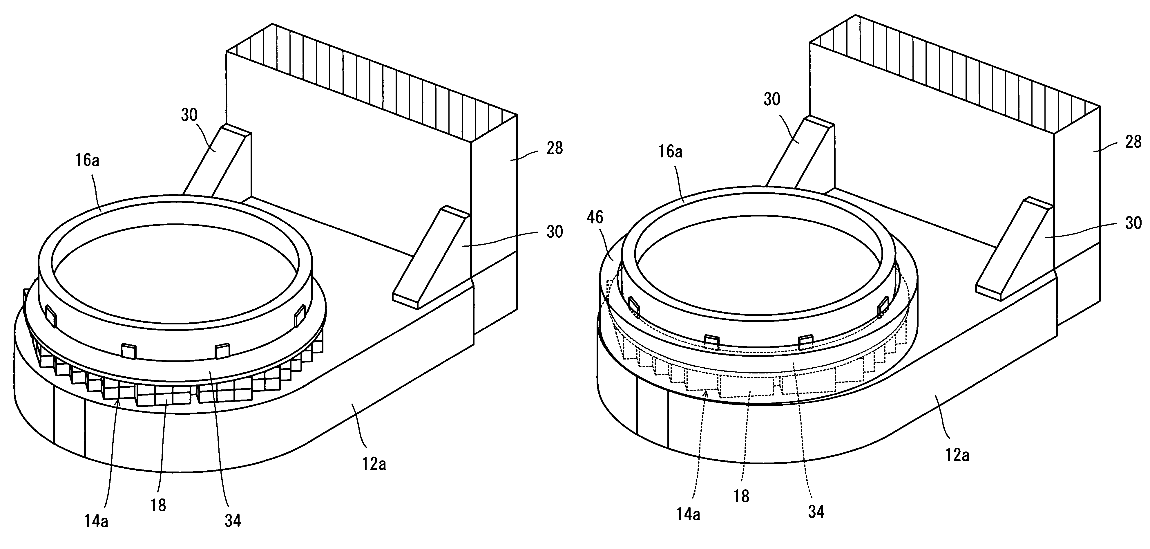
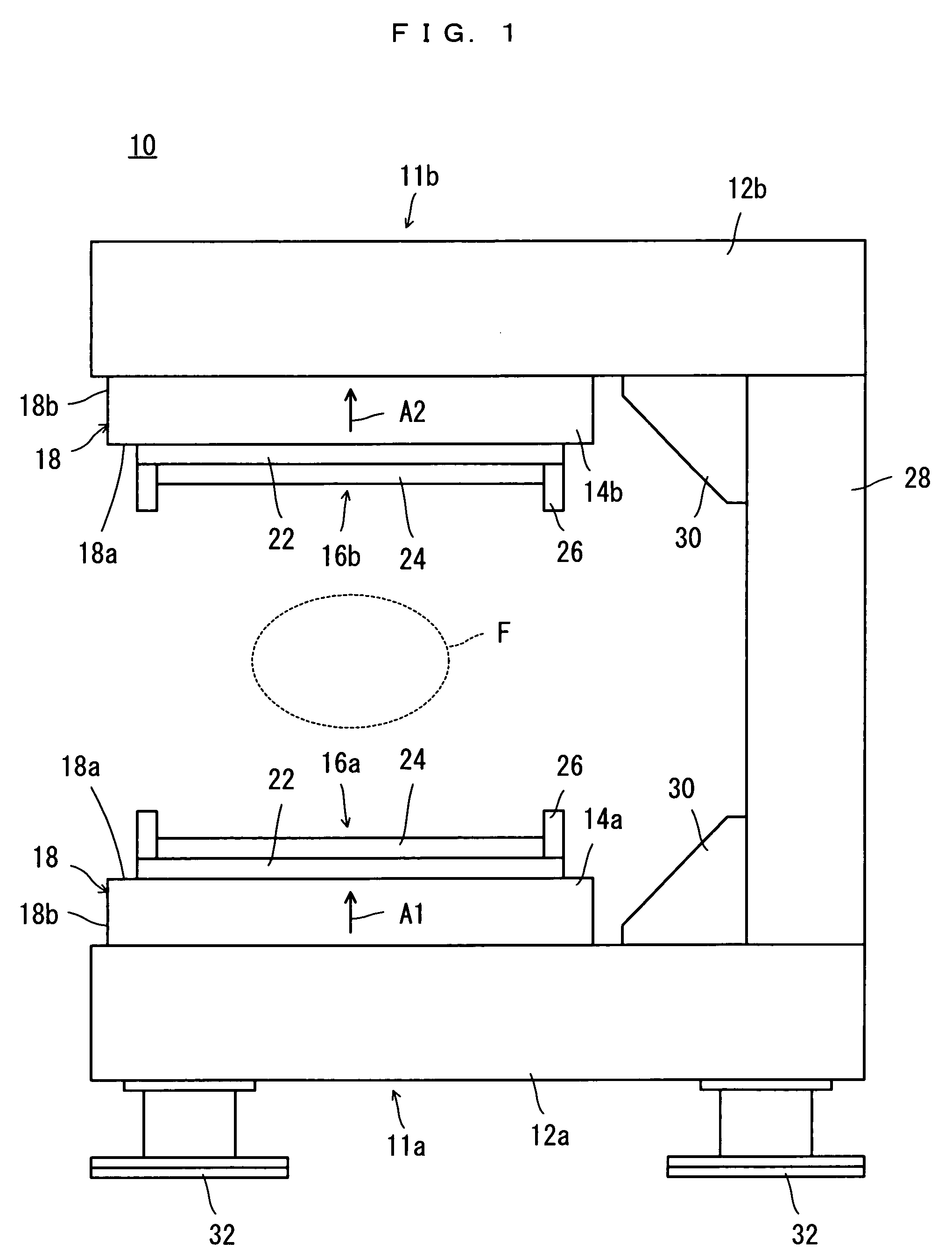
[0055]Referring to FIG. 1, a magnetic field generator for MRI 10 as an embodiment of the present invention is an open type magnetic field generator for an MRI apparatus, and includes a pair of magnetic pole units 11a and 11b opposed to each other with a space in between.

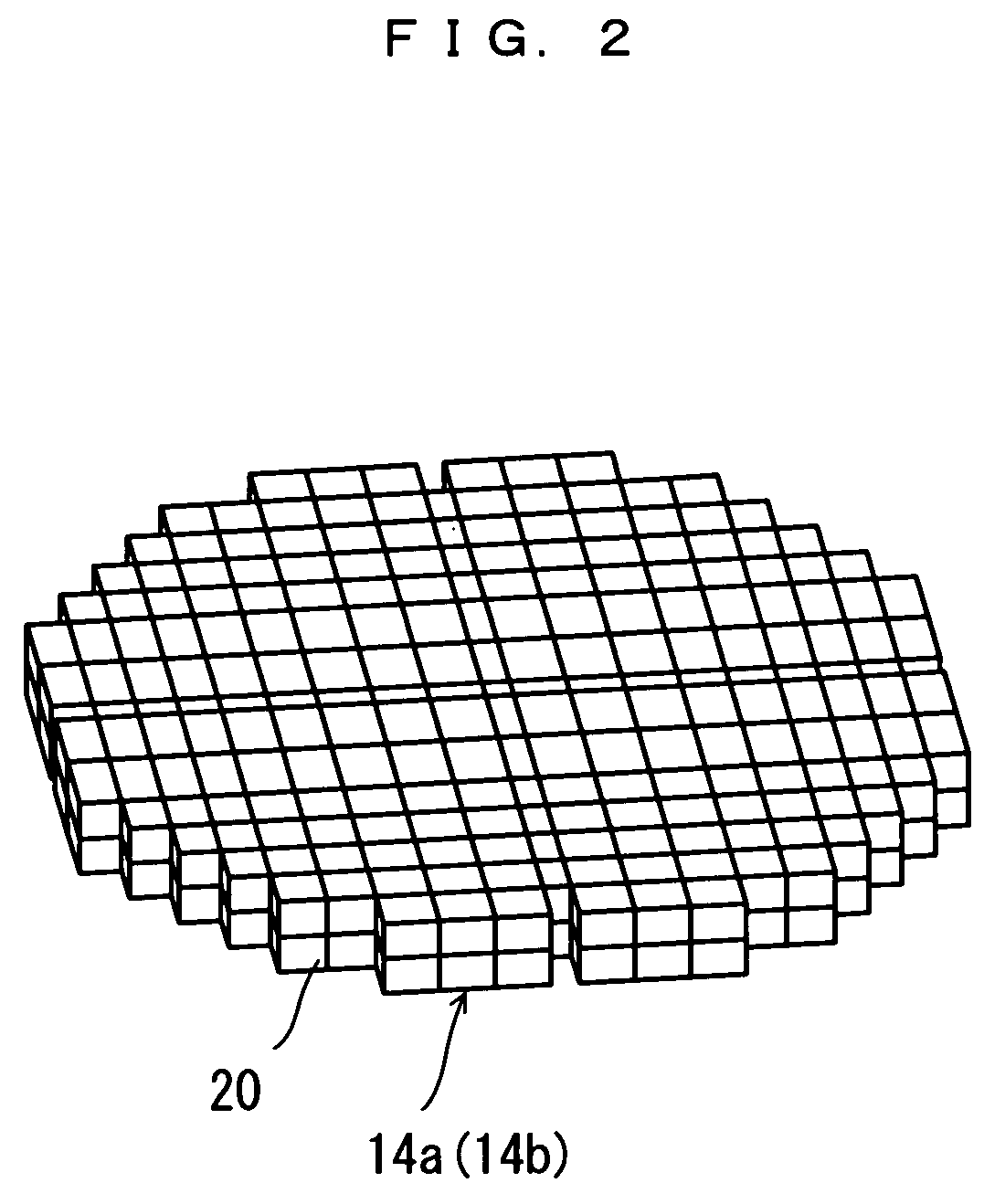
[0056]The magnetic pole units 11a and 11b include plate yokes 12a and 12b respectively. The pair of plate yokes 12a and 12b have opposed surfaces provided with permanent magnet groups 14a and 14b respectively. The permanent magnet groups 14a and 14b have opposed surfaces provided with pole pieces 16a and 16b fixed thereto respectively.

[0057]In this constitution, an outer circumferential portion of the permanent magnet group 14a extends more outward than the area of contact with the pole piece 16a, to become a projection 18, while an outer circumferential portion of the permanent magnet group 14b extends more outwa...


PUM

PropertyMeasurementUnit
heightaaaaaaaaaa
angleaaaaaaaaaa
magnetic fieldaaaaaaaaaa

Abstract

There is provided a magnetic field generator for MRI 10 applicable to a variety of magnetic field generators, and capable of preventing separation of permanent magnets 20 which constitute permanent magnet groups 14a, 14b. The magnetic field generator for MRI 10 includes a pair of permanent magnet groups 14a, 14b. The pair of permanent magnet groups 14a, 14b each including a plurality of permanent magnets 20 bonded to each other, are opposed to each other with a space in between. The permanent magnet groups 14a, 14b have projections 18 projecting more outward than the area of contact with respective pole pieces 16a, 16b. A flange-shaped member 34 is attached to each outer circumferential surface of the pole pieces 16a, 16b, covering a space-facing surface 18a of the projection 18.

Description

TECHNICAL FIELD[0001]The present invention relates to magnetic field generators for MRI, and more specifically to a magnetic field generator for MRI which has a projection made by a permanent magnet group projecting more outward than a pole piece contacted therewith.BACKGROUND ART[0002]Conventionally, in a permanent magnet type magnetic field generator for MRI, permanent magnets which constitute a permanent magnet group are bonded to adjacent permanent magnets, a plate yoke or both of these, with adhesive.[0003]However, such a construction may not be able to hold the permanent magnets which constitute the permanent magnet group sufficiently when the permanent magnet group is subjected to a mechanical load exceeding a normal design value due to vibration, impact, etc. during transportation of the magnetic field generator, and therefore can allow the permanent magnets to be separated from the adjacent permanent magnets or the plate yoke, or to detach from the permanent magnet group. I...

Claims


Application Information

Patent Timeline
Patent Type & Authority Patents(United States)
IPC IPC(8): H01F7/02
CPCG01R33/3802G01R33/3806G01R33/383
Inventor HASHIMOTO, SHIGEOAOKI, MASAAKI
Owner HITACHI METALS LTD
Why Eureka
Try Eureka