Method for transferring crop material

a crop material and transfer method technology, applied in the direction of threshers, digger harvesters, diggers, etc., can solve the problem that the speed attained by the working units is typically not adequate to convey the crop material

Active Publication Date: 2010-09-21
CLAAS SELBSTFAHRENDE ERNTEMASCHINEN GMBH
View PDF8 Cites 31 Cited by
  • Summary
  • Abstract
  • Description
  • Claims
  • Application Information

AI Technical Summary

Benefits of technology

[0008]More particularly, it is an object of the present invention to provide a method for transferring crop material from a harvesting machine to a transport vehicle, and a corresponding control unit for a harvesting machine, and a harvesting machine with a control unit of this type that increases the energy efficiency of the transfer.
[0012]According to the present invention, it is ensured that—in deviation from common practice, according to which the crop material is always accelerated to the highest speed possible—the acceleration of the crop material to be transferred is controlled as a function of at least one parameter that represents a transfer distance. In this manner it can be ensured that, if the transfer distance is very great, the crop material will be accelerated to a high speed as usual, so that the target point is reached by the stream of crop material without significant loss. In transfer situations in which the crop material only needs to “fall out” of the conveyor chute, however, it is no longer necessary to greatly accelerate the crop material and expend excess energy for this purpose. This is attractive, in particular, because—as described initially—the transport vehicle is rarely driven behind the harvesting machine, so that a large transfer distance rarely needs to be covered. In most cases, however, i.e., whenever the transport vehicle is driven next to the harvesting machine, the transfer distance to be covered is short. As a result, a considerable amount of energy can be saved during a majority of the harvesting time using the method according to the present invention.
[0019]A further alternative is to control the air supply through the post-accelerating unit. With conventional forage harvesters, air is drawn in by the post-accelerator through ventilation openings located on the front ends of the post-accelerating drum and, as a result, air is injected into the flow of crop material. With a preferred exemplary embodiment of the present invention, it is now provided that the width of the air supply openings is adjustable in a stepped or continual manner, so that the quantity of air injected by the post-accelerator into the flow of crop of material can be regulated in a targeted manner. Preferably, this adjustment of the air supply openings can take place automatically with the aid of suitable adjusting elements.
[0024]The advantage of using the positions of the conveyor chute part and the discharge flap is that these positions are known anyway or they are already measured by sensors located on the harvesting machine and, as a result, no further expenditure is required to determine the transfer distance.

Problems solved by technology

The speed attained by the working units is typically not adequate to convey the crop material through the conveyor chute and, in particular, over a long distance through the air as a fast-moving stream of crop material.

Method used


Image

  • Method for transferring crop material
  • Method for transferring crop material
  • Method for transferring crop material

Examples


Embodiment Construction

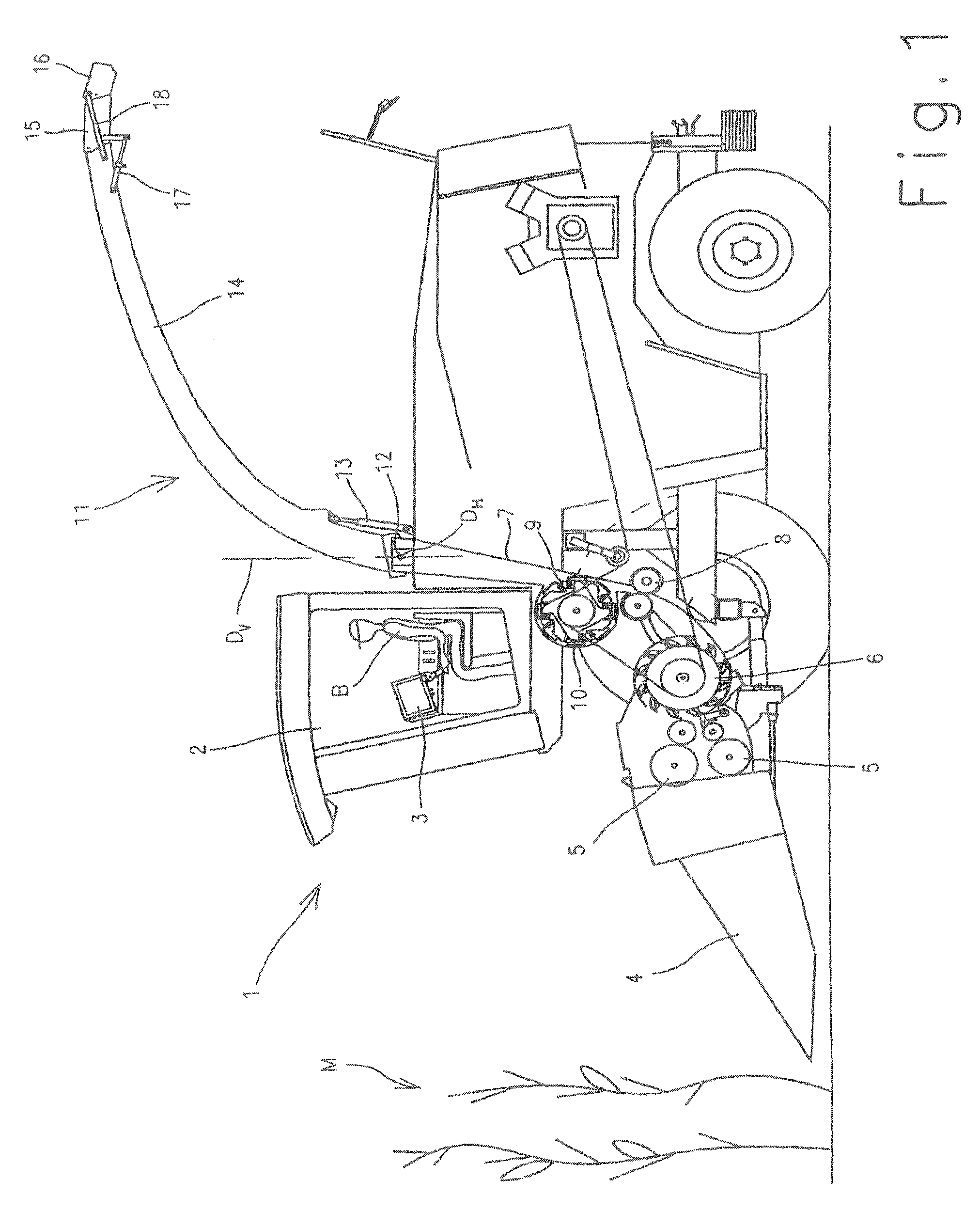
[0033]With the exemplary embodiments depicted in FIGS. 1 through 3, the harvesting machine is a forage harvester.

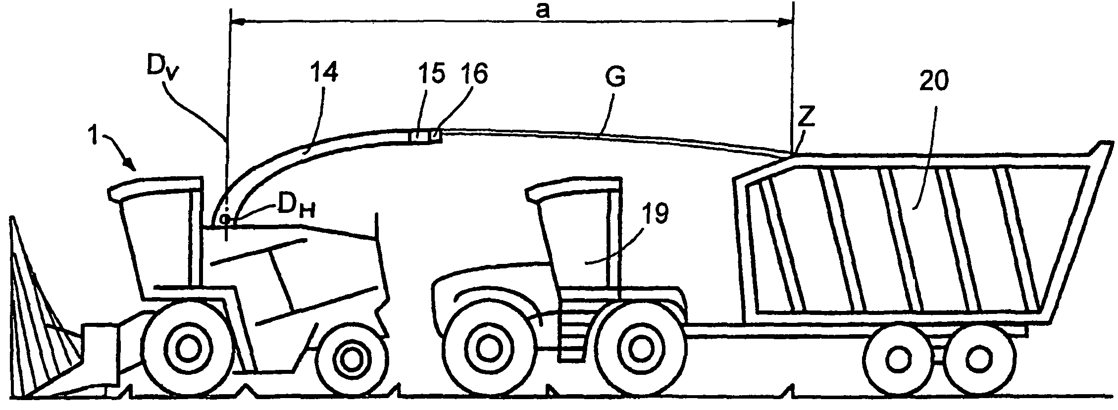
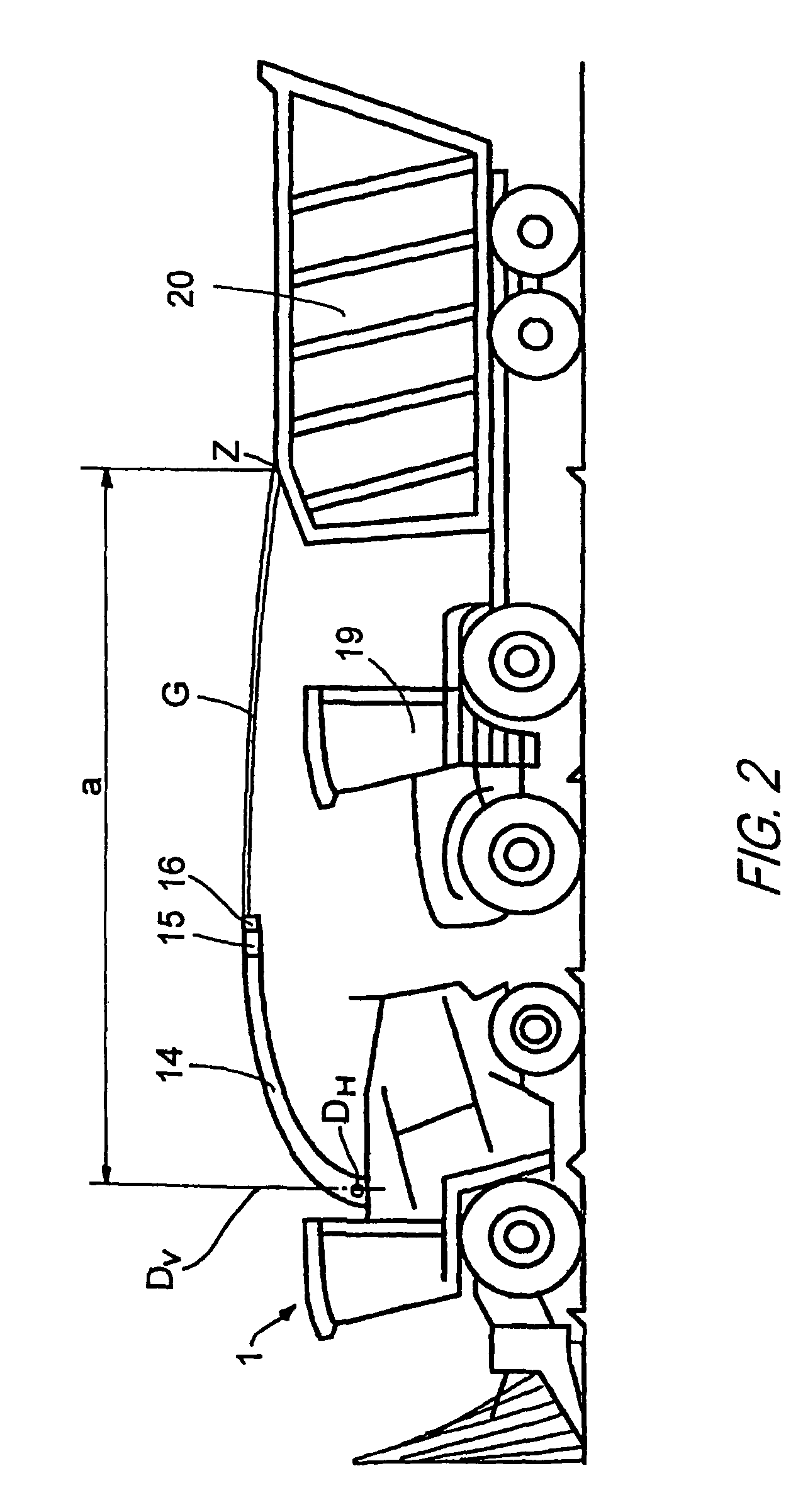
[0034]In FIG. 1, this forage harvester is equipped with a corn header 4 as a front attachment that cuts the corn M to be harvested at the bottom and then conveys it via feed drums 5 to a chopper drum 6. In this chopper drum 6, the corn plants are chopped in small pieces to a desired length of cut and guided further to a conditioning device 8, a “corn cracker”8, that ensures that the corn kernels are cracked. Corn cracker 8 conveys crop material G further upward into a conveyor chute 7, in which a post-accelerating drum 9 is located on the input side. Crop material G is post-accelerated by rotating post-accelerating drum 9 and ejected via transfer device 11 to a transport vehicle 20 (see FIGS. 2 and 3).

[0035]In this case, transfer device 11 is composed of an upper discharge chute 14 that abuts conveyor chute 7, upper discharge chute 14 forming an extended, movable conveyor...


PUM


Abstract

In a method for transferring crop material from a harvesting machine to a hauling vehicle, with which the crop material is accelerated and ejected through a conveyor chute of a transfer device to a target point on the transport vehicle, the acceleration of the crop material to be transferred is controlled as a function of at least one parameter that represents a transfer distance. A corresponding control unit for a harvesting machine and a harvesting machine with a control unit of this type is also provided.

Description

CROSS-REFERENCE TO A RELATED APPLICATION[0001]The invention described and claimed hereinbelow is also described in German Patent Application DE 10 2005 038 553.2 filed on Aug. 12, 2005. This German Patent Application, whose subject matter is incorporated here by reference, provides the basis for a claim of priority of invention under 35 U.S.C. 119(a)-(d).BACKGROUND OF THE INVENTION[0002]The present invention relates to a method for transferring crop material from a harvesting machine to a hauling vehicle, with which the crop material is accelerated and ejected through a conveying shaft of a transfer device to a target point on the transport vehicle.[0003]The present invention also relates to a corresponding control unit for a harvesting machine, and a harvesting machine, in particular a forage harvester, with a transfer device and a control unit of this type.[0004]Self-propelled harvesting machines, such as forage harvesters, combine harvesters or the like typically include a transf...

Claims


Application Information

Patent Timeline
Patent Type & Authority Patents(United States)
IPC IPC(8): A01D17/02
CPCA01D43/086
Inventor ISFORT, HEINRICH
Owner CLAAS SELBSTFAHRENDE ERNTEMASCHINEN GMBH
Why Eureka
Try Eureka