Apparatus and methods for repairing the function of a diseased valve and method for making same

a diseased valve and apparatus technology, applied in the field of apparatus and methods for repairing the function of a diseased valve, can solve the problems of chronic venous insufficiency, incompetent venous valve, and so severe congenital valve abnormalities

Active Publication Date: 2010-09-21
THE CLEVELAND CLINIC FOUND
View PDF38 Cites 45 Cited by
  • Summary
  • Abstract
  • Description
  • Claims
  • Application Information

AI Technical Summary

Problems solved by technology

Venous valves can become incompetent and lead to chronic venous insufficiency.
Congenital valve abnormalities may be so severe that emergency surgery is required within the first few hours of life, or they may be well-tolerated for many years only to develop a life-threatening problem in an elderly patient.
The two major problems that can develop with cardiac valves are stenosis, in which a valve does not open properly, and insufficiency (also called regurgitation), in which a valve does not close properly.
Stenosis and insufficiency may occur concomitantly in the same valve or in different valves.
Both of these abnormalities increase the workload and stress placed on the heart.
If this occurs on the valves of the left side (i.e., the systemic circulation side) of the heart, embolization results in sudden loss of the blood supply to the affected body organ and immediate malfunction of that organ.
Their main disadvantage is that they require the patient to take systemic anticoagulation drugs for the rest of his or her life, because of the propensity of mechanical valves to cause blood clots to form on them.
The main disadvantage of these valves is that they are not available in sufficient numbers to satisfy the needs of patients who need new aortic or pulmonary valves.
Homograft valves are also extremely expensive and can be more difficult to implant than either mechanical valves or tissue valves.
This operation exposes the patient to many risks especially in the elderly population.

Method used


Image

  • Apparatus and methods for repairing the function of a diseased valve and method for making same
  • Apparatus and methods for repairing the function of a diseased valve and method for making same
  • Apparatus and methods for repairing the function of a diseased valve and method for making same

Examples


first embodiment

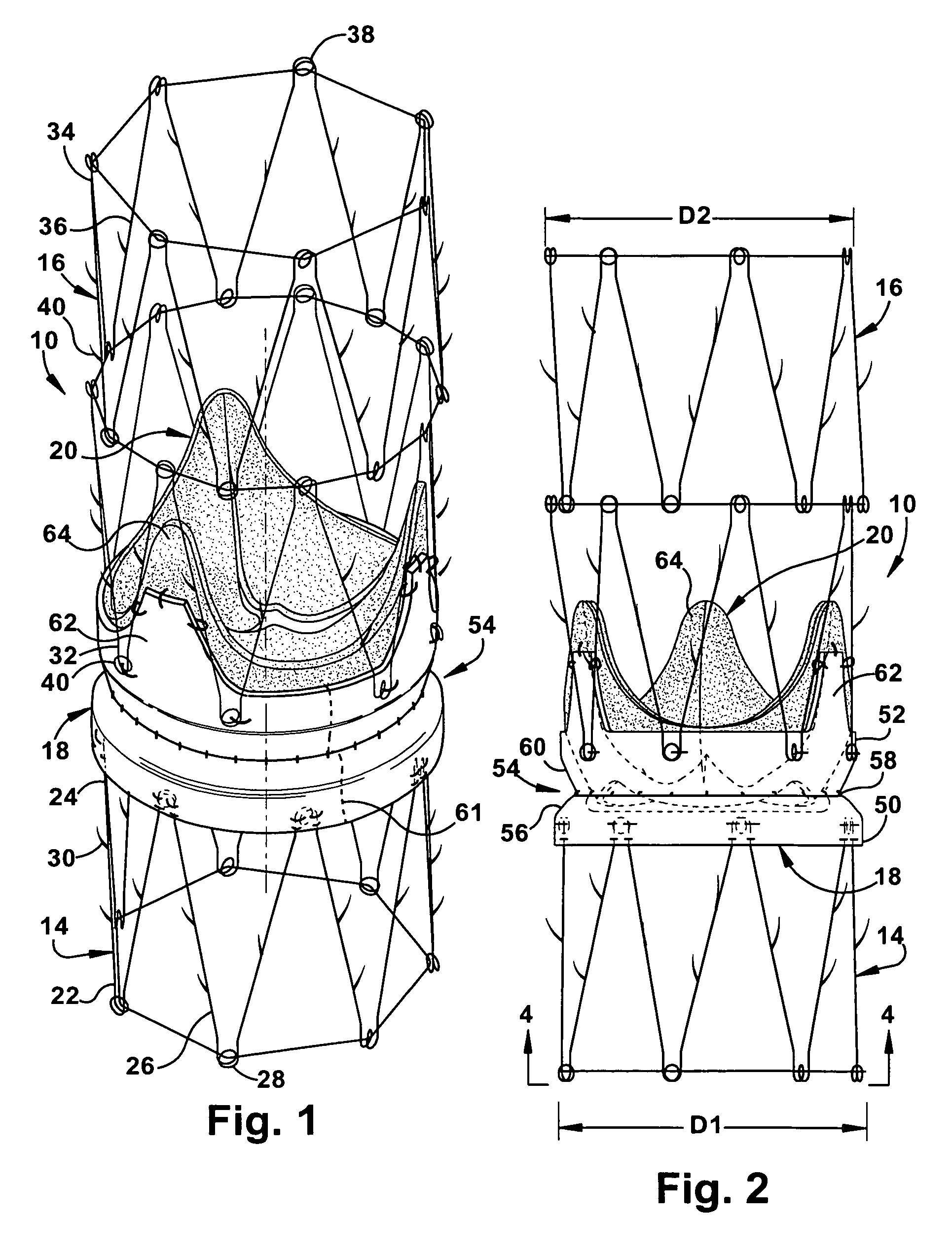
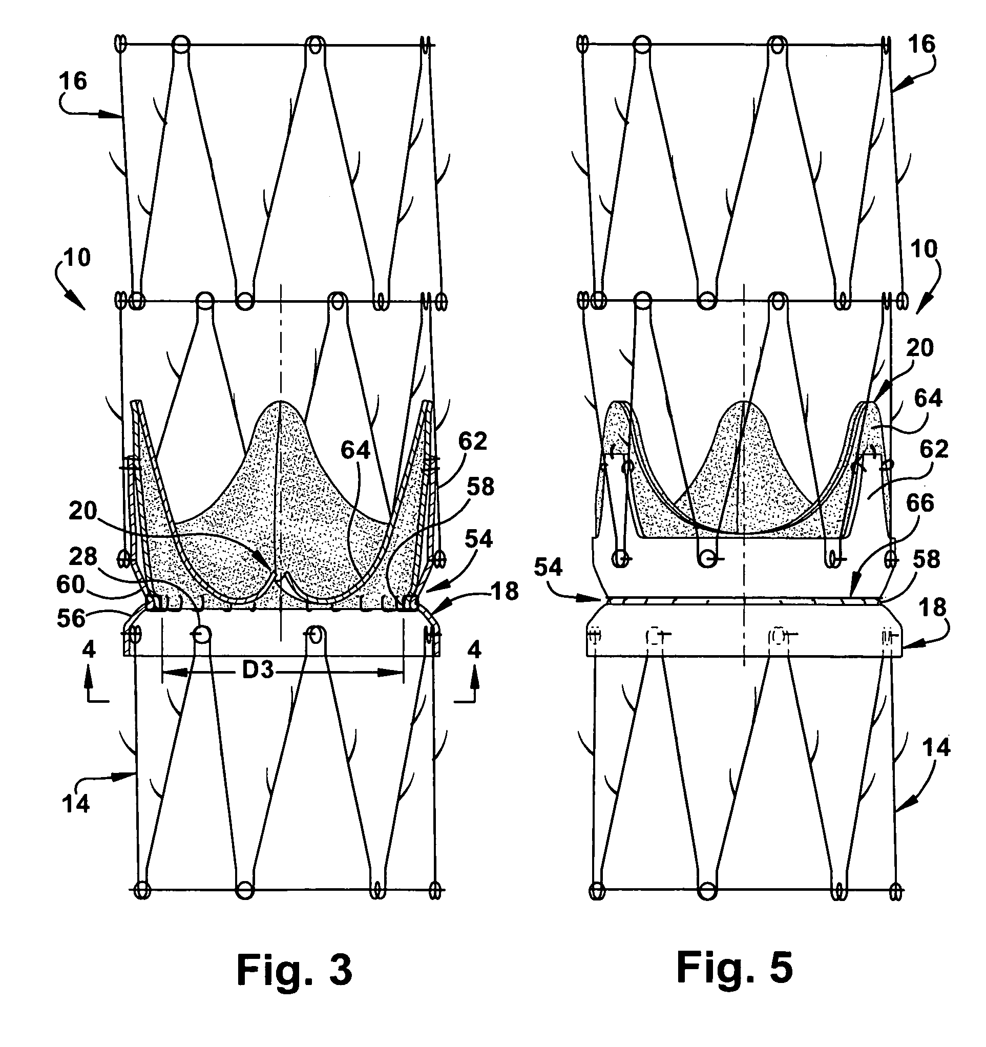
[0046]The present invention is directed to an apparatus and methods for repairing the function of a diseased valve, such as a cardiac or venous valve, via an endovascular technique, and is further directed to methods for making the apparatus. As representative of the present invention, FIGS. 1-4 illustrate an apparatus 10 for repairing the function of a diseased cardiac valve, such as a tricuspid valve 12 shown schematically in FIGS. 6-8. It should be apparent, however, to those skilled in the art that the apparatus 10 disclosed herein can also be used to repair the function of other cardiac valves as well as venous valves. The apparatus 10 includes annular first and second support members 14 and 16, a tubular graft section 18 interconnecting the support members, and a prosthetic valve 20 secured within the graft section.

[0047]The first support member 14 comprises a self-expanding or balloon expandable stent made from stainless steel, but could alternatively be made from any suitabl...

second embodiment

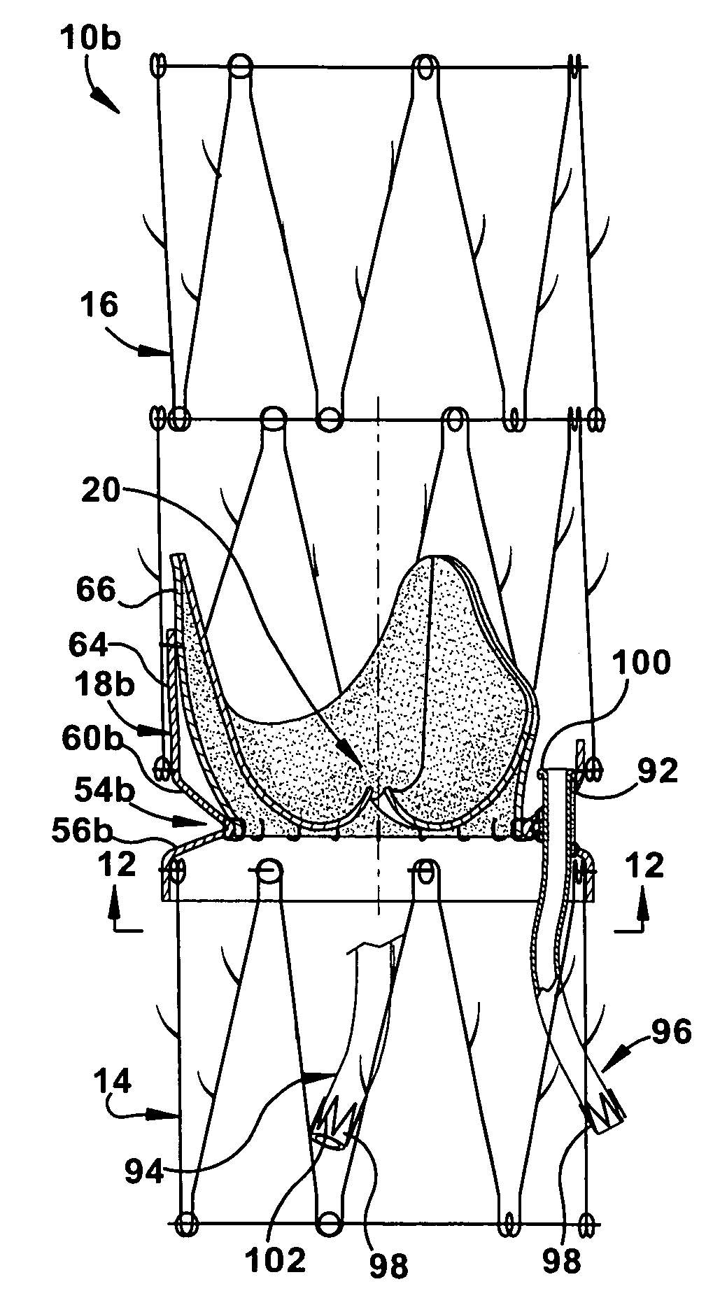
[0083]FIG. 13 illustrates placement of the apparatus 10b in accordance with the second embodiment to repair the function of a diseased aortic valve. It should be noted that it may be desirable to excise the native aortic leaflets prior to implantation of the apparatus 10b. To enable delivery and deployment of the apparatus, the apparatus 10b is radially collapsed and loaded into a sheath (not shown) over a catheter (not shown). Carotid or subclavian access may be used to cannulate the aorta (AO) and each of the two coronary arteries (CA).

[0084]After de-airing of the assembly, the apparatus 10b is introduced into the aorta. Under fluoroscopic and / or transesophageal echocardiographic guidance, the apparatus 10b is advanced to the desired location above the annulus of the native aortic valve. Wires placed within the coronary arteries may be loaded through guides (not shown) in the conduits 94 and 96 to ensure proper orientation. The sheath is retracted to allow the first and second sup...

fifth embodiment

[0096]The primary difference between the apparatus 10e of FIGS. 16-17 and the apparatus 10 of FIGS. 1-4 is that the second end portion 52 of the graft section 18 further includes a plurality of extension stents 62e that extend axially toward the distal end 34 of the second support member 16, in lieu of the extension flaps 62 of the previously described apparatus 10. The extension stents 62e are each connected, such as by sutures, to one of the leaflets 64 of the bioprosthetic valve 20 and may act to support the leaflets 64 in a desired manner. The number and circumferential orientation of the extension stents 62e should correspond to the number and orientation of leaflets 64 in the bioprosthetic valve 20. It is contemplated that the Nitinol ring 66, previously described with regard to FIG. 5, could also be used in FIGS. 16-17 to anchor the extension stents 62e. Conversely, the extension stents 62e could be directly anchored, via sutures or the like, to the second end portion 52 of t...


PUM


Abstract

An apparatus for repairing the function of a diseased valve includes an annular first support member expandable to a first diameter. An annular second support member is spaced axially apart from the first support member and is expandable to a second diameter that is independent of the first diameter. A tubular graft section interconnects the first and second support members. The graft section defines an annulus having a third diameter that is independent of each of the first and second diameters. A prosthetic valve is secured within the annulus of the graft section. The bioprosthetic valve has at least two valve leaflets that are coaptable to permit the unidirectional flow of blood. Methods for repairing the function of a diseased valve and for making the apparatus are also provided.

Description

RELATED APPLICATION[0001]This application claims the benefit of U.S. Provisional Patent Application Ser. No. 60 / 682,939, filed on May 20, 2005, the subject matter of which is incorporated herein by reference.FIELD OF THE INVENTION[0002]The present invention is directed to an apparatus and methods for repairing the function of a diseased valve, such as a cardiac or venous valve, via an endovascular technique, and is further directed to methods for making the apparatus.BACKGROUND OF THE INVENTION[0003]It is known to implant prosthetic valves in various body passages to replace native valves that are diseased or otherwise defective in some manner. Blood pressure, as provided by heart activity via the arteries, is normally sufficient to maintain the flow of blood in one direction through the vasculature. The blood pressure in the veins is much lower than in the arteries and venous valves function to limit the backflow of blood through the veins. Numerous such venous valves are located t...

Claims


Application Information

Patent Timeline
Patent Type & Authority Patents(United States)
IPC IPC(8): A61F2/24
CPCA61F2/2418A61F2/2475A61F2/2409A61F2230/0017A61F2220/0008A61F2220/0016A61F2220/0066A61F2/856
Inventor GREENBERG, ROY K.
Owner THE CLEVELAND CLINIC FOUND
Why Eureka
Try Eureka