System and method for spinal fusion

a spinal fusion and system technology, applied in the field of spinal fusion system and method, can solve the problems of reduced disc vertical height, increased biomechanical stress on the posterior side of the spine, and decreased viscoelastic properties

Inactive Publication Date: 2010-09-21
AEOLIN
View PDF295 Cites 468 Cited by
  • Summary
  • Abstract
  • Description
  • Claims
  • Application Information

AI Technical Summary

Benefits of technology

[0011]The current invention is directed to a system and method for fusing a first and second vertebrae. In one embodiment, the vertebrae are fused by inserting a self-broaching interbody device into a disc space without the need for separately drilling and broaching. The self-broaching interbody device may include cutting flutes or other broaching means capable of cutting through the cartilaginous endplates of the vertebrae˜exposing subchondial bone, facilitating fusion development.
[0012]In another embodiment, an interbody device with an expanding means is inserted into the disc space. The expanding means is capable of moving the interbody device from an unexpanded state, where the upper and lower surfaces of the interbody device are at a first distance from each other, to an expanded state, where the upper and lower surfaces are at a second and greater distance from each other. In the unexpanded state, the interbody device can be inserted between the vertebrae while they are in an undistracted state without the need for previously distracting the disc space. In the expanded state, the inserted interbody device can force the first and second vertebrae into a distracted state.

Problems solved by technology

This degeneration causes a reduction in the vertical height of the disc, and a diminution of its viscoelastic properties.
This results in increased biomechanical stress on the posterior side of the spine.
Arthritic changes in the facet joints following disc degeneration can cause mechanical back pain.
If they become excessive, these arthritic changes can cause spinal stenosis.
Such grafts were only able to support around 430 lbs. of force within the disc space, however, and compression forces up to 1,850 lbs. can be experienced by a human when, for example, bending over to pick up a 25 lb. chi
ld. After experiencing such high compression forces, these grafts tended to collapse and lose their ability to fix and stabilize the spinal motion segment by distracting the disc sp
The process of separately broaching and distracting the disc space, however, requires multiple steps of inserting and removing various drills, broaches and / or distracters into the disc space, causing direct or indirect damage to the load-bearing endplates of the adjacent vertebrae, weakening them and jeopardizing the fixation of the interbody fusion construction.
Because of the openings in the cages, another problem with the prior art cages were that small pieces of bone or ortho-biological material were capable of spilling out of the cage and into the soft tissue surrounding the surgical opening before the cage was placed between the vertebral endplates.
In this case, heterotrophic ossification, or bone growth, could occur in the access port of the surgical wound or possibly near the exiting segmental nerve, resulting in bony nerve entrapment and tremendous pain and complications.
These U-shaped devices, however, typically broke due to the forces exerted by the round object and the adjacent vertebrae.
In addition to the above problems with inserting the prior art cages, the cages are susceptible to movement within the disc space once they are inserted.
This movement can damage the biological growth of the fusion, due to shear forces on the vascular ingrowth nourishing the endosteal bone growth—limiting the development of fusion of the bone inside of the cage which is necessary to stabilize the adjacent vertebrae, resulting in looseness and bone graft collapse.
To this effect, several prior art cages were constructed with short spikes or points to stabilize them within the disc space, but which were not long enough to broach through the cartilage into the boney tissue of the vertebrae.
Moreover, if the compression forces are not withstood and the disc space is not held in a distracted state by a strong cage, the cage may collapse, leading to looseness, instability and further failure of fusion due to movement.
However, if the cage is overly rigid and strong, such as a threaded cage, it may shield the bone inside of the cage from the normal stresses and strains that bone needs to develop into weight bearing, trabecular bone, which will fuse with the adjacent vertebrae in a strong and rigid fashion.
This failure to satisfactorily promote fusion may also lead to looseness and instability of the cage or fusion construct.

Method used


Image

  • System and method for spinal fusion
  • System and method for spinal fusion
  • System and method for spinal fusion

Examples


Embodiment Construction

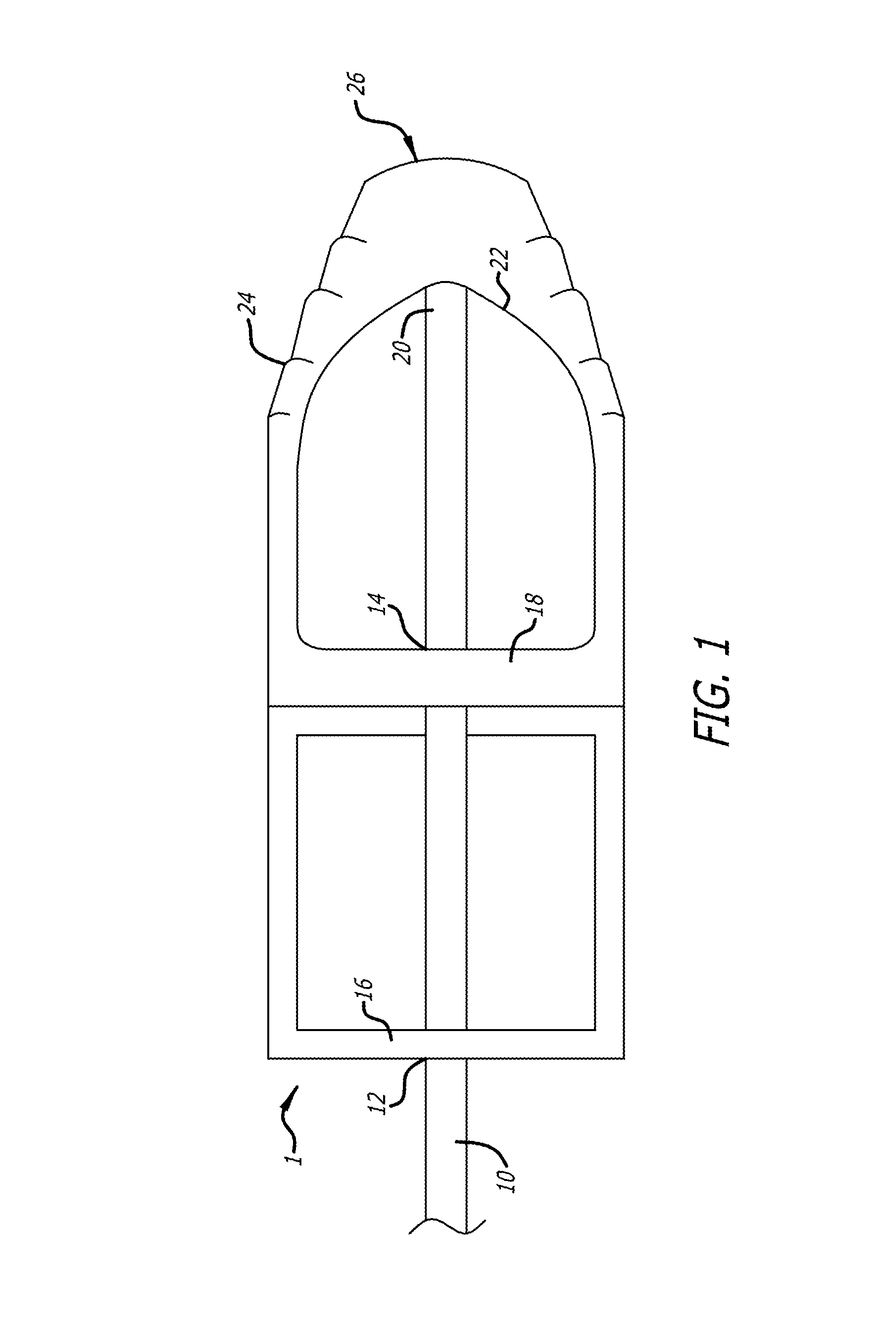
[0027]FIG. 1 shows a top view of an interbody cage 1 and an insertion rod 10. The cage 1 includes a substantially square and hollow main portion 2 and a nose 26. Bone graft with biological materials, such as morphogenic protein and derivatives, can be placed inside of the cage 1 to allow the cage 1 to be fused and incorporated into the boney structure of the adjacent vertebrae once the cage 1 is inserted.

[0028]The insertion rod 10 projects through axial openings 12 and 14 of the back wall 16 and middle septum 18, respectively, of the cage 1. A distal end 20 of the insertion rod 10 abuts an internal, distal end 22 of the cage 1, and is shaped to match the internal, distal end 22 of the cage 1. This shape serves to evenly distribute an insertion force exerted by the insertion rod 10 onto the internal, distal end 22 of the cage 1.

[0029]The middle septum 18 of the cage L comprises a rigid girder fixed to the interior surface of the cage 1 and located in a plane transverse to the project...


PUM

PropertyMeasurementUnit
diameteraaaaaaaaaa
heightaaaaaaaaaa
heightaaaaaaaaaa

Abstract

The current invention is directed to a system and method for fusing two adjacent vertebrae. In one embodiment, the vertebrae are fused by inserting a self-broaching interbody apparatus into a disc space without the need for separately drilling and broaching. The self-broaching interbody apparatus may include cutting flutes or other broaching means capable of cutting through the cartilaginous endplates of the vertebrae. In another embodiment, an interbody apparatus with an expanding means capable of distracting the disc space between the adjacent vertebrae is inserted into the disc space. Another embodiment includes a sleeve that fits around an interbody apparatus that has at least one opening in its outer surface leading to a cavity filled with bone and / or ortho-biological materials.

Description

BACKGROUND[0001]As the lumbar spine ages, disc degeneration occurs. This degeneration causes a reduction in the vertical height of the disc, and a diminution of its viscoelastic properties. The profile of the spine also changes with age. The swayback curvature of youth becomes the flat-back of old age. This results in increased biomechanical stress on the posterior side of the spine.[0002]With a recent increased understanding in the biomechanics of the spine, it is acknowledged that maintenance of the normal curvature of the lumbar spine is preferable. When spinal fusions are considered, it is important to re-establish the normal biomechanical arrangement, and to restore the sagittal profile of the spine to obtain optimal results. Arthritic changes in the facet joints following disc degeneration can cause mechanical back pain. If they become excessive, these arthritic changes can cause spinal stenosis.[0003]For these reasons, several prior art techniques have been used that remove t...

Claims


Application Information

Patent Timeline
Patent Type & Authority Patents(United States)
IPC IPC(8): A61F2/44
CPCA61F2/4455A61F2/4611A61F2/30965A61F2002/2817A61F2002/2835A61F2002/30062A61F2002/3008A61F2002/30451A61F2002/30522A61F2002/30538A61F2002/30556A61F2002/30579A61F2002/30774A61F2002/30785A61F2002/30841A61F2002/30879A61F2002/4475A61F2002/448A61F2002/4627A61F2002/4629A61F2210/0004A61F2220/0025A61F2220/0058A61F2250/0006A61F2250/0009A61F2250/0098A61F2310/00017A61F2310/00023A61F2002/30593
Inventor MCKINLEY, LAURENCE M.
Owner AEOLIN
Why Eureka
Try Eureka