Semiconductor circuit

a technology of semiconductors and circuits, applied in the direction of semiconductor devices, basic electric elements, electrical equipment, etc., can solve the problems of large chip area consumed by laterally oriented devices, 64-bit computer chips will need more devices, and require expensive advances in lithography and manufacturing equipmen

Inactive Publication Date: 2010-09-21
BESANG
View PDF31 Cites 213 Cited by
  • Summary
  • Abstract
  • Description
  • Claims
  • Application Information

AI Technical Summary

Benefits of technology

[0022]The present invention employs a method of forming a semiconductor circuit, which includes providing a carrier substrate which carries an interconnect region, and providing a donor layer coupled to a donor substrate with a detach layer. The donor layer is coupled to the carrier substrate through the interconnect region, and the donor substrate is decoupled from the detach layer so the donor layer is carried by the carrier substrate. An electronic device is formed with the donor layer after the donor layer is coupled to the carrier substrate. In this way, the electronic device is not exposed to heat used to couple the donor layer to the carrier substrate.
[0023]In some embodiments, the donor layer consists essentially of a semiconductor material before the donor layer is coupled to the carrier substrate. In some embodiments, the donor layer does not include any electronic devices before the donor layer is coupled to the carrier substrate. In this way, the donor layer does not include any electronic devices that are exposed to heat when coupling the donor layer to the carrier substrate. In some embodiments, the interconnect region includes a refractory metal so that it is less likely to be degraded in response to being exposed to the heat used to form the bonding interface.

Problems solved by technology

However, these laterally oriented devices consume significant amounts of chip area.
However, the 64-bit computer chip will need more devices since there are more bits to process at a given time.
The number of devices can be increased by making the devices included therein smaller, but this requires expensive advances in lithography and manufacturing equipment.
However, the yield of the computer chips fabricated in a run decreases as their area increases, which increases the overall cost.
However, there are several problems with doing this.
One problem is that the masks used to fabricate the memory devices are typically not compatible with the masks used to fabricate the other devices on the computer chip.
Hence, it is more complex and expensive to fabricate a computer chip with memory embedded in this way.
Another problem is that memory devices tend to be large and occupy a significant amount of area.
The total area of the computer chip can be increased, but as discussed above, this decreases the yield and increases the cost.

Method used


Image

  • Semiconductor circuit
  • Semiconductor circuit
  • Semiconductor circuit

Examples


Embodiment Construction

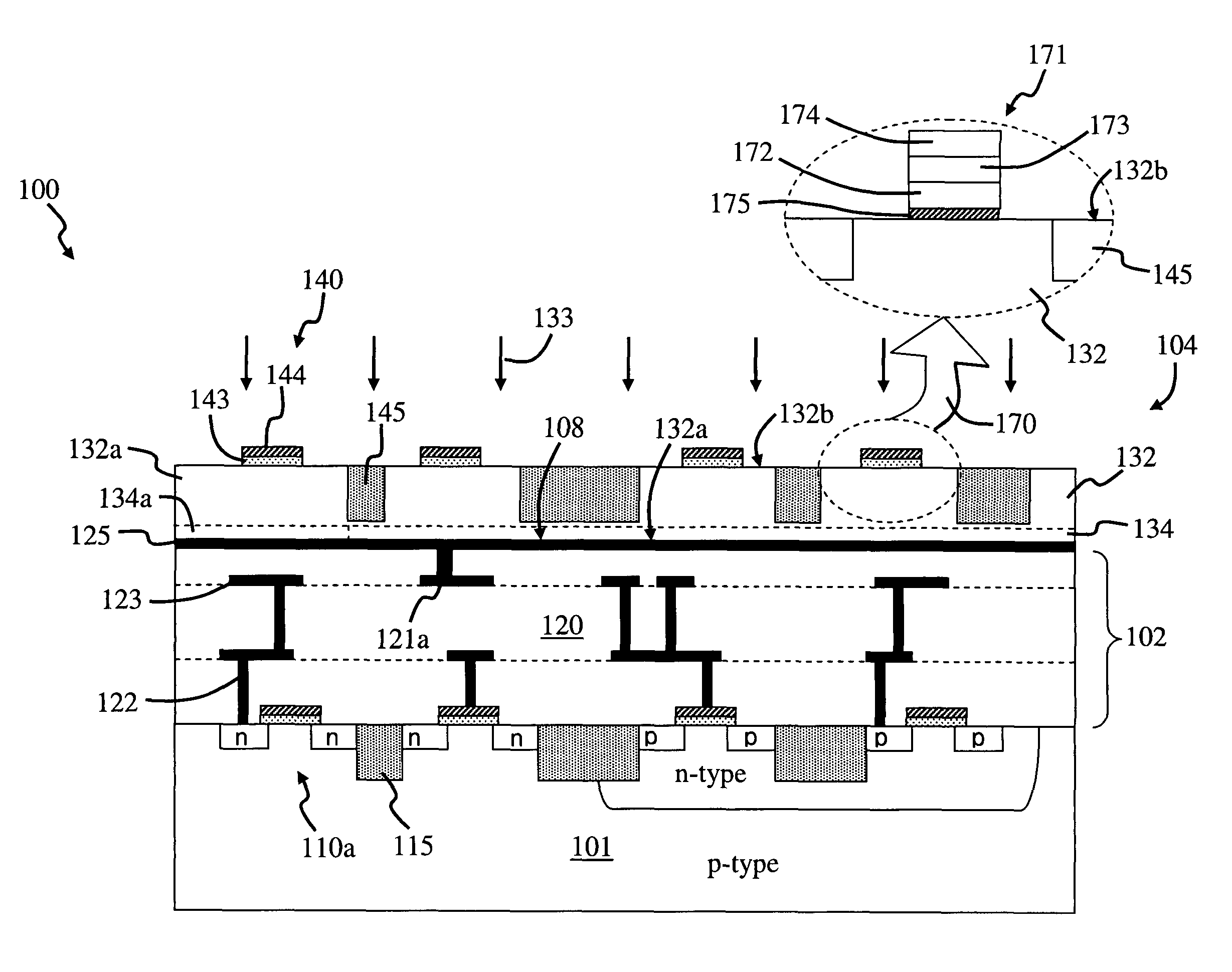
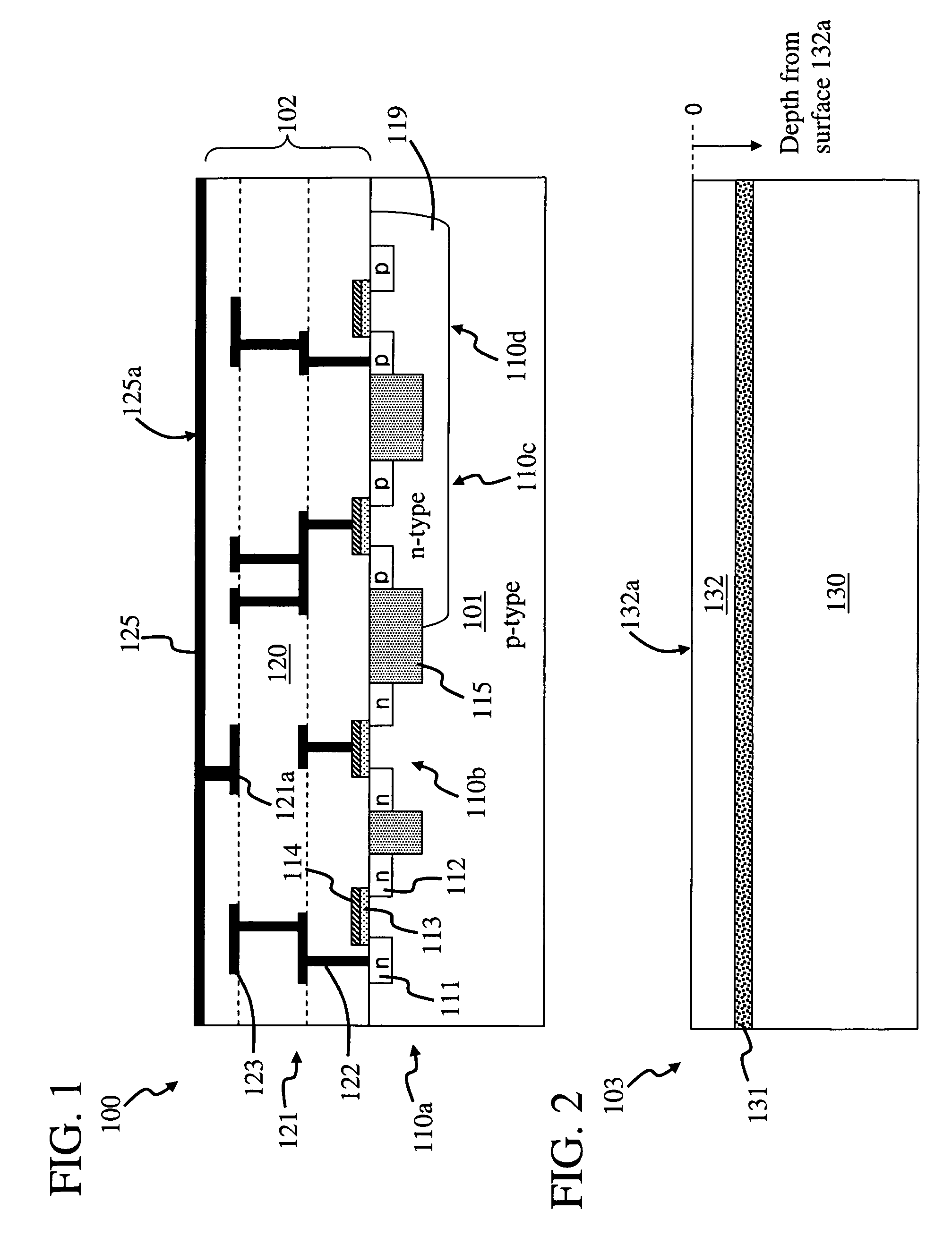
[0030]FIGS. 1-9 are sectional views of steps in forming a semiconductor circuit 100. Semiconductor circuit 100 can be included in a computer chip having a memory region carried by a carrier substrate, wherein the carrier substrate generally has electronic circuitry formed therewith. The carrier substrate is typically a semiconductor substrate, which includes a semiconductor material such as silicon.

[0031]In some embodiments, the electronic circuitry formed with the carrier substrate includes processor and / or control circuitry. The processor circuitry processes data, such as digital data, and the control circuitry controls the flow of the data, such as sending it to and retrieving it from the memory region. The electronic circuitry can include many different types of electronic devices, such as metal-oxide semiconductor field effect transistors (MOSFET). One type of electronic circuitry often used is referred to as complementary MOSFET (CMOS) circuitry.

[0032]The memory region can inc...


PUM


Abstract

A semiconductor memory device includes a substrate and an interconnect region carried by the substrate. A donor layer is coupled to the interconnect region through a bonding interface. An electronic device is formed with the donor layer, wherein the electronic device is formed after the bonding interface is formed. A capacitor is connected to the electronic device so that the electronic device and capacitor operate as a dynamic random access memory device.

Description

CROSS-REFERENCE TO RELATED APPLICATIONS[0001]This is a continuation-in-part of, and claims the benefit of, U.S. patent application Nos.:[0002]Ser. No. 11 / 092,498, filed on Mar. 29, 2005,[0003]Ser. No. 11 / 092,499, filed on Mar. 29, 2005,[0004]Ser. No. 11 / 092,500, filed on Mar. 29, 2005,[0005]Ser. No. 11 / 092,501, filed on Mar. 29, 2005;[0006]Ser. No. 11 / 092,521, filed on Mar. 29, 2005;[0007]Ser. No. 11 / 180,286, filed on Jul. 12, 2005;[0008]Ser. No. 11 / 378,059, filed on Mar. 17, 2006; and[0009]Ser. No. 11 / 606,523, filed on Nov. 30, 2006;which in turn are continuation-in-parts of, and claim the benefit of, U.S. patent application Ser. No. 10 / 873,969 (now U.S. Pat. No. 7,052,941), filed on Jun. 21, 2004, which claims the benefit of Republic of Korea Patent Application Nos. 10-2003-0040920 and 10-2003-0047515, filed on Jun. 24, 2003 and Jul. 12, 2003, respectively, the contents of all of which are incorporated herein by reference in their entirety.[0010]This is also a continuation-in-part...

Claims


Application Information

Patent Timeline
Patent Type & Authority Patents(United States)
IPC IPC(8): H01L21/46
CPCH01L21/2007H01L21/8221H01L24/83H01L27/0688H01L27/11551H01L24/29H01L2224/291H01L2224/8385H01L2924/01005H01L2924/01013H01L2924/01015H01L2924/01018H01L2924/01027H01L2924/01029H01L2924/01038H01L2924/01042H01L2924/01056H01L2924/01073H01L2924/01074H01L2924/01075H01L2924/01078H01L2924/01079H01L2924/07802H01L2924/13091H01L2924/14H01L2924/1433H01L2924/19041H01L2924/19042H01L2924/19043H01L2924/30105H01L2924/3011H01L2924/01006H01L2924/01033H01L25/18H10B41/20
Inventor OH, CHOONSIKLEE, SANG-YUN
Owner BESANG
Why Eureka
Try Eureka