Bendable heat spreader with metallic wire mesh-based microstructure and method for fabricating same

a heat spreader and microstructure technology, applied in indirect heat exchangers, semiconductor/solid-state device details, lighting and heating apparatus, etc., can solve the problems of not being able to use heat pipes independently, not being able to form trenches on a micro scale over copper plates, and devices inevitably generating more heat than befor

Inactive Publication Date: 2006-05-11
TAIWAN MICROLOOPS CORP
View PDF14 Cites 64 Cited by
  • Summary
  • Abstract
  • Description
  • Claims
  • Application Information

AI Technical Summary

Benefits of technology

[0021] wherein bonded surfaces between the metallic meshes and the inner surfaces of the metallic housing, the upper cover and the lower cover, and the reinforcing members and the inner surfaces of the metallic housing all are diffusion-bonded interfaces.
[0022] According to a preferred embodiment of the present invention, the material forming the metallic housing and reinforcing members is copper or aluminum and the reinforcing members is in the shape of post or strip.

Problems solved by technology

These devices inevitably generate more heat than before, particularly under the demand of high-speed computation.
However, since this kind of heat pipe cannot be used independently, another kind of independent plate type heat pipe, also called a “heat spreader”, has been developed.
However, it is not so easy to form trenches on a micro scale over the copper plate.
In contrast, though copper-powder sintering would be easier for forming the capillary structure, it is difficult to control the final sintering quality, which results in higher scrap rates and thus higher fabrication costs.
In addition, in case where bending the heat spreader is needed, the capillary structure formed by copper-powder sintering would be damaged due to the bending.
However, this approach only allows soldering each of the supports at one end while the other end of the supports cannot be soldered after the housing has been sealed.
This may result in deformation of the housing due to the heat generated during the soldering operation.

Method used


Image

  • Bendable heat spreader with metallic wire mesh-based microstructure and method for fabricating same
  • Bendable heat spreader with metallic wire mesh-based microstructure and method for fabricating same
  • Bendable heat spreader with metallic wire mesh-based microstructure and method for fabricating same

Examples


Embodiment Construction

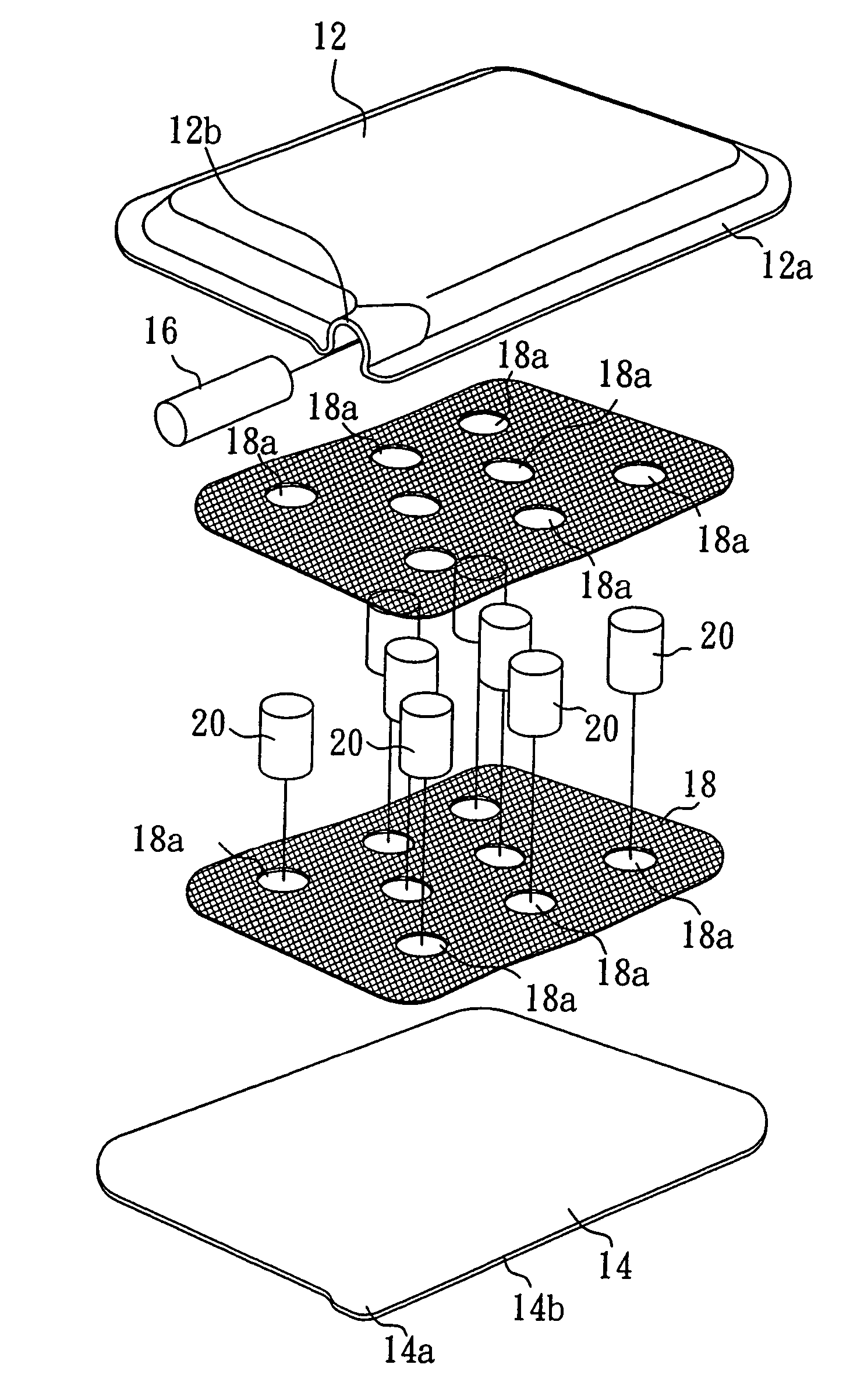
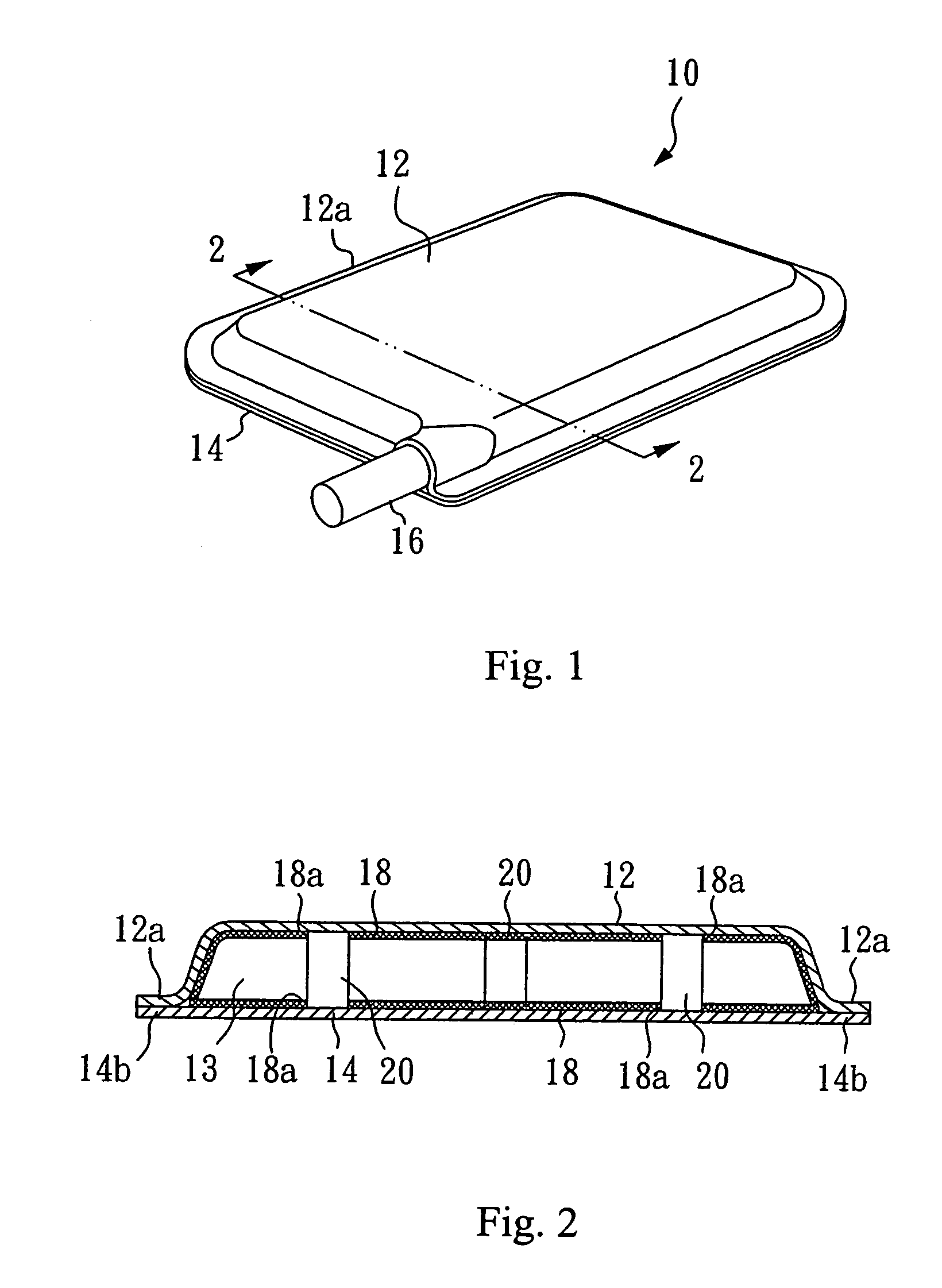
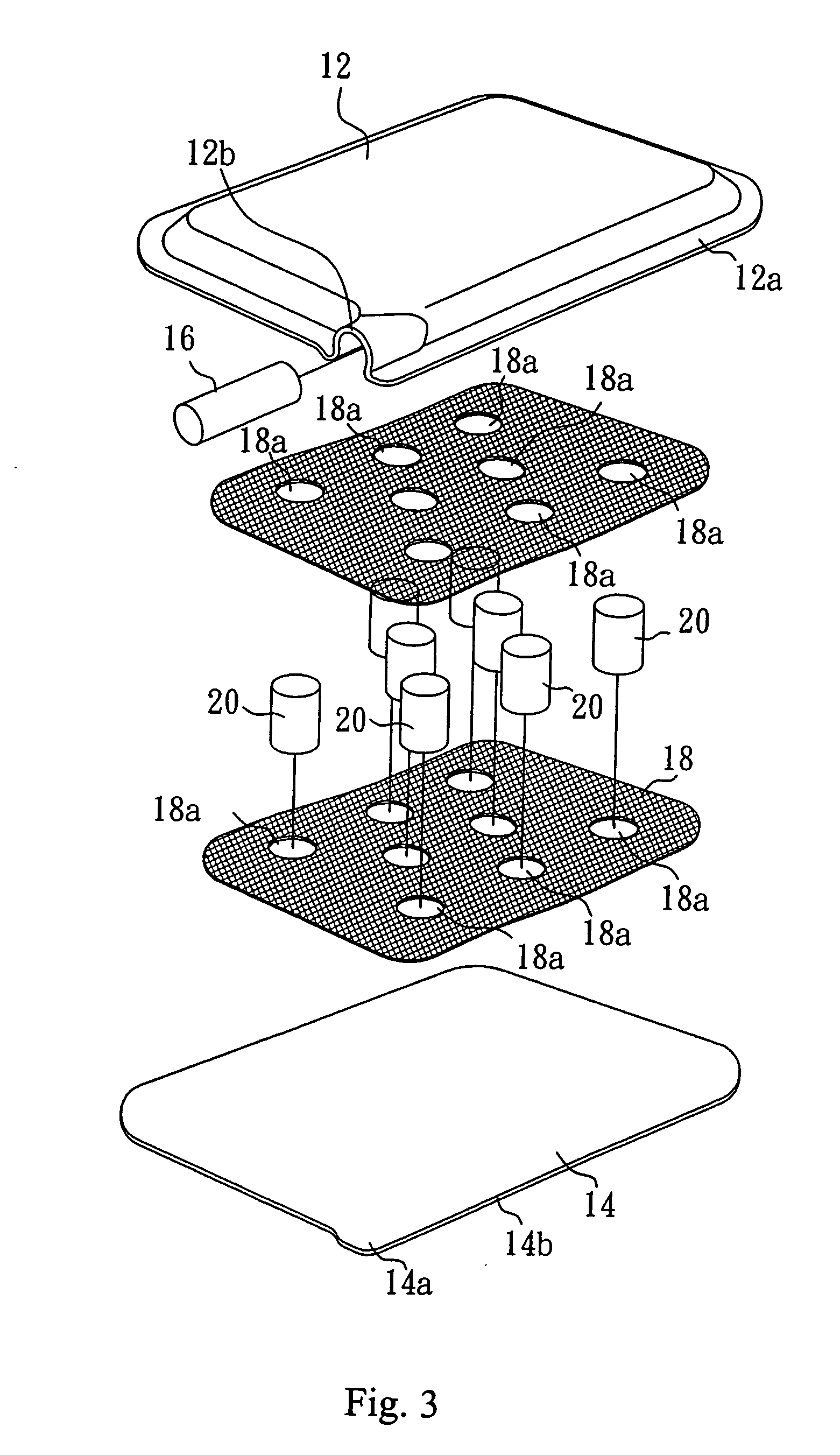
[0038]FIG. 1 illustrates a heat spreader 10 in accordance with the present invention. The heat spreader 10 comprises an upper cover 12, a lower cover 14 and a filling pipe 16. The material used for these components generally is copper, while any other metals, such as aluminum, can also be used as long as they having good heat-dissipating capability.

[0039]FIGS. 2 and 3 illustrate the heat spreader 10 in accordance with a first embodiment of the present invention. The upper cover 12 and lower cover 14 each have a perimeter 12a, 14b, respectively. A portion within the perimeter 12a of upper cover 12 protrudes slightly. A hermetically sealed cavity 13 is formed by diffusion bonding between the perimeters of the upper cover 12 and lower cover 14. An appropriate volume of working fluid (e.g., pure water, not shown) can be filled in the cavity 13 via the filling pipe 16, one end of which is in fluid communication with the cavity 13, while the other end is sealed after the cavity 13 has be...


PUM

PropertyMeasurementUnit
pressureaaaaaaaaaa
temperatureaaaaaaaaaa
pressureaaaaaaaaaa

Abstract

The present invention discloses a heat spreader and method for making the heat spreader. The heat spreader comprises: a hollow metallic housing including an upper cover having an inner surface and a lower cover having an inner surface, the upper and lower covers being bonded together along their perimeters defining a cavity; a capillary structure in a form of metallic meshes bonded to the inner surfaces of the upper and lower covers of the metallic housing; a plurality of reinforcing members disposed in the cavity and bonded between the inner surfaces of the upper and lower covers of the metallic housing; and a working fluid receive in the cavity; wherein bonded surfaces between the metallic meshes and the inner surfaces of the metallic housing, the upper cover and the lower cover, and the reinforcing members and the inner surfaces of the metallic housing all are diffusion-bonded interfaces.

Description

FIELD OF THE INVENTION [0001] The present invention relates to a heat spreader and method for fabricating same, and more particularly, to a bendable heat spreader with metallic meshes-based microstructure, for example, copper meshes, and method for fabricating same. BACKGROUND OF THE INVENTION [0002] Recent electronic appliances such as personal computers, communication devices, TFT-LCD, etc. adopt a variety of electronic devices which generate heat in operation. These devices inevitably generate more heat than before, particularly under the demand of high-speed computation. Therefore, preventing electronic devices from degrading performance due to overheating becomes extremely important, and a variety of cooling devices and methods are developed for this purpose. [0003] For example, a cooler with heat pipe(s) attached to a copper plate has been used in the industry. However, since this kind of heat pipe cannot be used independently, another kind of independent plate type heat pipe,...

Claims


Application Information

Patent Timeline
Patent Type & Authority Applications(United States)
IPC IPC(8): H05K7/20F28D15/02F28D15/04H01L23/427
CPCF28D15/0233F28D15/046H01L23/427Y10T29/4935H01L2924/0002H01L2924/00B21D53/00
Inventor LEE, KUO-YINGCHIU, CHIEN-WENLIN, CHIEN-HUNGSU, CHERNG-YUH
Owner TAIWAN MICROLOOPS CORP
Why Eureka
Try Eureka