Endoscope apparatus

a technology of endoscope and endoscope, which is applied in the direction of color television, catheter, television system, etc., can solve the problems of deteriorating image quality, complicated circuit configuration, and in principle redundant conversion processing

Inactive Publication Date: 2010-09-21
FUJI PHOTO OPTICAL CO LTD
View PDF11 Cites 58 Cited by
  • Summary
  • Abstract
  • Description
  • Claims
  • Application Information

AI Technical Summary

Benefits of technology

[0009]The present invention has been made in view of the above problem, and an object of the invention is to provide a user-friendly endoscope apparatus capable of forming a spectral image directly from Y / C signals and also obtaining a spectral image from either Y / C signals or RGB signals.

Problems solved by technology

Such color conversion processings are in principle redundant, and such a problem is brought about whereby repeated color conversion may cause deterioration in quality of images and complicate the circuit configuration.

Method used


Image

  • Endoscope apparatus
  • Endoscope apparatus
  • Endoscope apparatus

Examples


embodiment 1

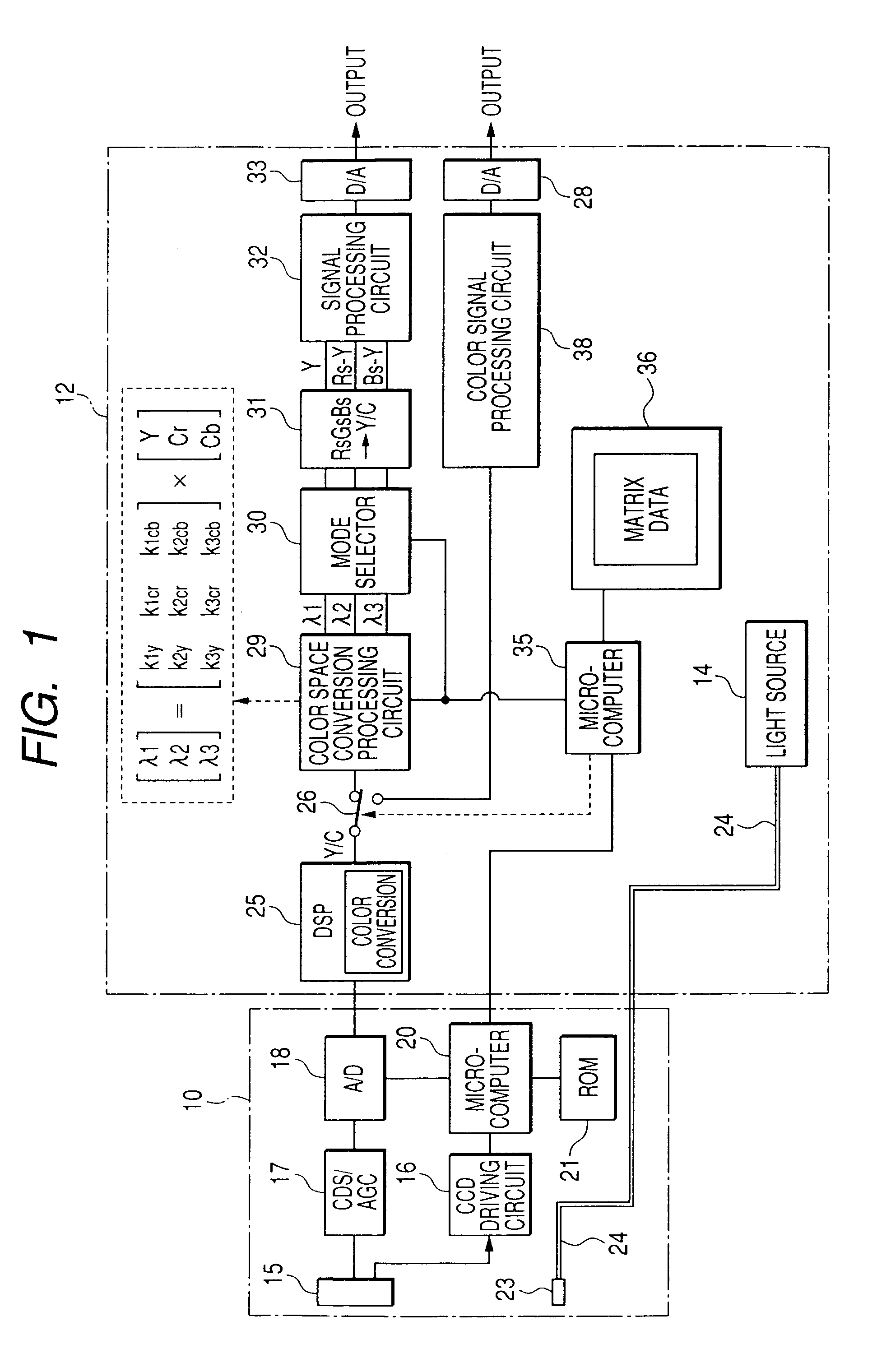
[0019]FIG. 1 shows a constitution of the electronic endoscope apparatus of the As shown in FIG. 1, the electronic endoscope apparatus is constituted so that a scope (electronic endoscope) 10 is connected to a processor unit 12 in a freely attachable and detachable way and a light source 14 is arranged on the processor unit 12. Further, there is a case where the light source 14 is arranged on a light source unit, which is a separate body. The scope 10 is provided on the end with a CCD 15 which is a solid imaging device, and a complementary color-type CCD having, for example, color filters of Mg, Ye and Cy are used as the CCD 15 on an imaging surface.

[0020]The CCD 15 is provided with a CCD driving circuit 16 for forming a driving pulse on the basis of synchronizing signals, a CDS / AGC (correlated dual sampling / automatic gain control) circuit 17 for sampling and amplifying an image (video) signal input from the CCD 15 the image signal and an A / D converter 18. Also provided are a microc...

embodiment 2

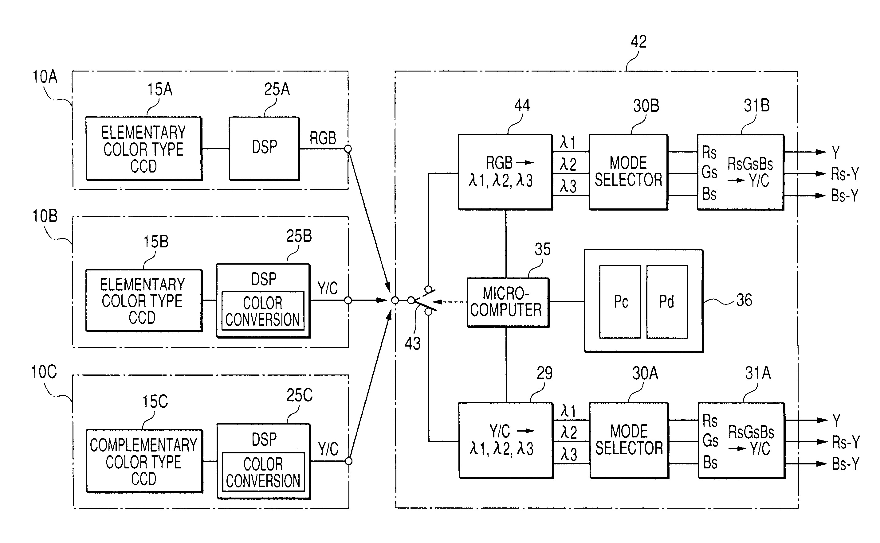
[0046]The embodiment 2 is constituted as described above. When any one of the scopes 10A to 10C shown in FIG. 4 is connected to the processor unit 42, the microcomputer 35 of the processor unit 42 makes communications with the microcomputer (20) of the scopes 10A to 10C, thereby obtaining the identification information on the signal output mode of these scopes. When the selector 43 is changed on the basis of the information and the scope 10A is connected, a color space conversion processing circuit 44 is selected. In this instance, RGB matrix data Pd is read from the memory 36, and a spectral image is formed by λ1, λ2 and λ3 signals of three wavelength ranges (three-color mode) or of one wavelength range (monochrome mode) selected by the matrix data Pd and RGB signals.

[0047]On the other hand, where the scope 10B or 10C, is connected, the selector 43 selects the color space conversion processing circuit 29. In this instance, Y / C matrix data Pc is read from the memory 36, and a spectr...


PUM


Abstract

An endoscope apparatus comprises: an endoscope comprising an imaging device that forms color image signals of a body to be observed; a Y / C signal processing circuit that forms brightness / color difference signals from a color image signal obtained by the imaging device; a storage portion that stores Y / C matrix data for forming a spectral image based on the brightness / color difference signals; and a Y / C spectral image forming circuit that conducts matrix calculation by the Y / C matrix data of the storage portion and the brightness / color difference signals output from the Y / C signal processing circuit and forms a spectral image of an arbitrarily selected wavelength range.

Description

[0001]This Nonprovisional application claims priority under 35 U.S.C. §119(a) on Patent Application No(s). JP 2005-060199 filed in Japan on Mar. 4, 2005, the entire contents of which is hereby incorporated by reference.BACKGROUND OF THE INVENTION[0002]1. Field of the Invention[0003]The present invention relates to an endoscope apparatus, more particularly, a constitution used in medical fields for forming and displaying a spectral image (video) made up of image information of arbitrarily selected wavelength ranges.[0004]2. Description of the Related Art[0005]Recently, in a electronic endoscope apparatus which uses a solid imaging device, spectral imaging combined with a narrow band pass filter on the basis of a spectral reflectance in alimentary canal (gastric mucosa and the like), namely, a narrow band filter built-in an electronic endoscope apparatus (Narrow Band Imaging-NBI) has become the focus of attention. In place of rotational filters of R (red), G (green) and B (blue) by a ...

Claims


Application Information

Patent Timeline
Patent Type & Authority Patents(United States)
IPC IPC(8): H04N13/00H04N5/228
CPCA61B1/00009A61B1/045A61B1/05A61B5/0084A61B1/000094
Inventor TAKEUCHI, SHINJIABE, KAZUNORIAYAME, DAISUKE
Owner FUJI PHOTO OPTICAL CO LTD
Why Eureka
Try Eureka