Image display apparatus and in-vehicle image display apparatus

a technology of image display and in-vehicle display, which is applied in the direction of lighting and heating equipment, identification means, instruments, etc., can solve the problems of increased crosstalk influence, reduced focal distance, and increased curvature, so as to reduce crosstalk and uneven illumination. , the effect of low cos

Active Publication Date: 2010-09-21
OLYMPUS CORP
View PDF14 Cites 13 Cited by
  • Summary
  • Abstract
  • Description
  • Claims
  • Application Information

AI Technical Summary

Benefits of technology

[0012]The present invention has been made to solve the problems described above, and is directed to provide an image display apparatus and an in-vehicle image display apparatus capable of obtaining high-quality images with a little crosstalk and a little unevenness of illumination at low cost.

Problems solved by technology

However, in the time sharing illumination type stereoscopic display apparatus disclosed in Japanese Patent No. 3072866, the range which enables proper observation is narrow, and there has been a problem that especially when, for example, an observer on the right side has moved an observing position more to the right side during observation of an image on the right side, an image on the left side which is the image in the opposite direction is visible.
Furthermore, in an optical system using a lenticular, when right and left images are to be separated with a large angle, the focal distance has to be decreased, and the curvature is extremely increased, which entails an increased influence of aberration, so that there has also been a problem that the influence of the crosstalk increases accordingly.
Thus, the light guiding plate 153 has to have a structure subjected to a uniform surface treatment or a symmetrical structure, and there is a difference of illumination intensity between a part near the light sources 152-1 and 152-2 and a part far from the light sources 152-1 and 152-2, which appears as the unevenness of illumination, so that there has been a problem that the influence of the unevenness is greater especially in larger display images.

Method used


Image

  • Image display apparatus and in-vehicle image display apparatus
  • Image display apparatus and in-vehicle image display apparatus
  • Image display apparatus and in-vehicle image display apparatus

Examples


first embodiment

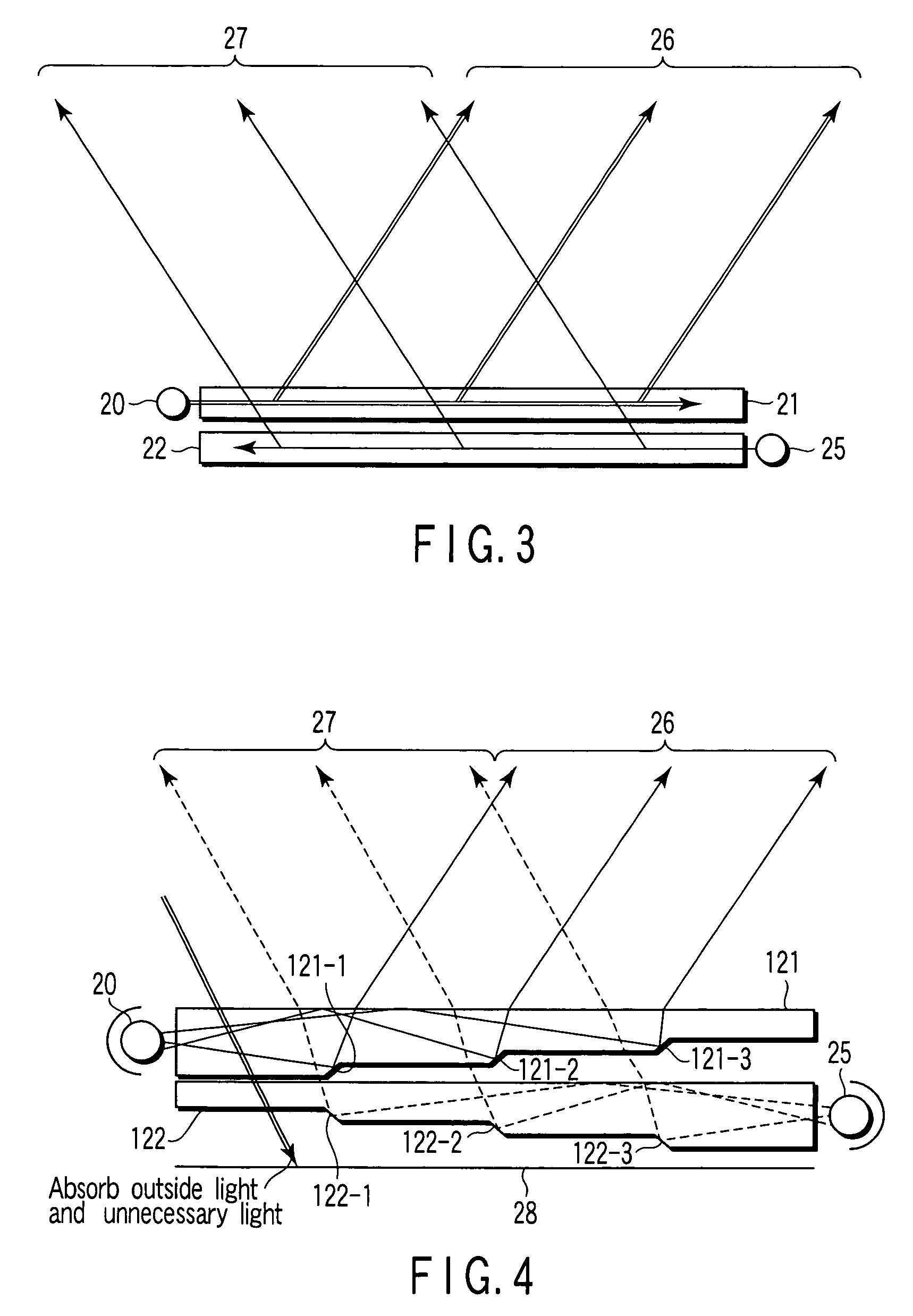
[0077]FIG. 4 is a schematic diagram showing a specific sectional structure of the illumination means according to the present invention. Here, as in the configuration of FIG. 3, a first light guiding plate 121 and a second light guiding plate 122 are arranged in a stacked state, there is a difference between the first light guiding plate 121 and the second light guiding plate 122 as to the positions where the first light source 20 and the second light source 25 are disposed.

[0078]Furthermore, in the rear surfaces of the light guiding plates 121 and 122, a plurality of slope portions 121-1 to 121-3 are provided to extend in the shape of streaks at predetermined intervals, and form step-like portions. The first light guiding plate 121 and the second light guiding plate 122 are the same in shape, but are different in a horizontal direction. A light absorbing member 28 for absorbing outside light and unnecessary light is disposed in the rear of the second light guiding plate 122.

[0079]L...

second embodiment

[0089]FIG. 8 is a schematic diagram showing a specific sectional structure of illumination means according to the present invention. Here, as in the configuration of FIG. 3, a first light guiding plate 221 and a second light guiding plate 222 are arranged in a stacked state, there is a difference between the first light guiding plate 221 and the second light guiding plate 222 as to the positions where the first light source 20 and the second light source 25 are disposed. Further, a plurality of grooves 221-1 to 221-3 and 222-1 to 222-3 are provided in the front surfaces of the light guiding plates 221 and 222, respectively.

[0090]Light exiting from the first light source 20 enters the first light guiding plate 221 from the end face of the first light guiding plate 221. Since the conditions of the total internal reflection are satisfied in the front and rear surfaces of the first light guiding plate 221, the light that has entered travels to an end face side opposite to the first ligh...

third embodiment

[0092]FIG. 9 is a schematic diagram showing a specific sectional structure of illumination means according to the present invention. Here, as in the configuration of FIG. 3, a first light guiding plate 321 and a second light guiding plate 322 are arranged in a stacked state. Although not shown in the drawing, a plurality of grooves as described with FIG. 8 are provided in the front surface of the light guiding plates 321 and 322.

[0093]First, the configuration of the first light guiding plate 321 will be described. Focusing attention on an end face 321-1 from which light from the first light source 20 enters and on the end faces of the groove portions from which the light exits, these end faces are parallel, so the first light guiding plate 321 has the same effects as when passing through a parallel plane plate. That is, the entrance angle coincides with the exit angle, so that if the optical axis of an illumination optical system 40 has a predetermined angle to the end face 321-1 of...


PUM

PropertyMeasurementUnit
frequencyaaaaaaaaaa
angleaaaaaaaaaa
angleaaaaaaaaaa

Abstract

An image display apparatus has one display screen configured to display images corresponding to a plurality of observers. The image display apparatus includes illumination unit for emitting a first light flux and a second light flux in at least two different directions in a time sharing manner, and a transmissive display element configured to display in a time sharing manner a first image using the first light flux as illumination light and a second image using the second light flux as illumination light. The illumination unit includes a first light source which emits the first light flux, a second light source which emits the second light flux, a first light guiding plate which projects the first light flux only in a direction to a first observer, and a second light guiding plate which projects the second light flux only in a direction to a second observer.

Description

[0001]This application is a U.S. National Phase Application under 35 USC 371 of International Application PCT / JP2005 / filed Jun. 24, 2005.TECHNICAL FIELD[0002]The present invention relates to an image display apparatus and an in-vehicle image display apparatus.BACKGROUND ART[0003]An image display apparatus has heretofore been known which has one display surface and by which images corresponding to viewing directions can be observed. For example, Japanese Patent No. 3072866 has disclosed a stereoscopic display apparatus using matrix-like illumination, a lenticular, etc. as a technique for switching the directivity of illumination in a time sharing manner in displaying images in accordance with the viewing directions.[0004](A) and (B) of FIG. 19 are diagrams showing one example of the configuration of a conventional image display apparatus, wherein time sharing illumination is carried out by the combination of a light source group 100 composed of divided light sources L1, R1 to L3, R3 ...

Claims


Application Information

Patent Timeline
Patent Type & Authority Patents(United States)
IPC IPC(8): G02F1/1335
CPCB60K35/00G02B6/0048G02B6/0076G02B27/2264G03B21/625G09F9/305B60K2350/2052B60K2350/206B60K2350/901B60K2350/903G02B6/0016G02B6/003G02B6/0038G02B6/0068B60K2370/20B60K2370/334B60K2370/736B60K2370/739G02B30/24
Inventor SUGIHARA, RYOHEIIBA, YOICHI
Owner OLYMPUS CORP
Why Eureka
Try Eureka