Kinematic optical mount

a technology of optical elements and mounts, applied in the field of components mounting, can solve the problems of increasing the complexity of proposed solutions of this type for providing pure axial translation adjustment is typically high, and the performance and accuracy of microlithography optical systems are increasingly demanding

Active Publication Date: 2010-09-21
CORNING INC
View PDF14 Cites 20 Cited by
  • Summary
  • Abstract
  • Description
  • Claims
  • Application Information

AI Technical Summary

Benefits of technology

[0015]It is an advantage of an embodiment of the present invention that it provides an optical mount apparatus that constrains motion in any direction but allows precision adjustment of position along the optical axis.

Problems solved by technology

Continuing improvements in miniaturization place increasingly more challenging demands on the performance and accuracy of the optical system used for this function.
Microlithography optical systems are fairly large and complex, containing a number of optical elements.
However, proposed solutions of this type for providing pure axial translation adjustment are typically highly complex, often requiring precision fabrication and assembly of multiple interconnecting parts.
With any type of solution for axial adjustment, even the slightest parasitic effects or asymmetries of construction can compromise the purity of motion demanded for lens adjustment in high-resolution photolithography.
Overall, conventional lens mounting methods are likely to cause overconstraint and other problems affecting purity of motion that limit their usefulness for photolithography applications.

Method used


Image

  • Kinematic optical mount
  • Kinematic optical mount
  • Kinematic optical mount

Examples


Embodiment Construction

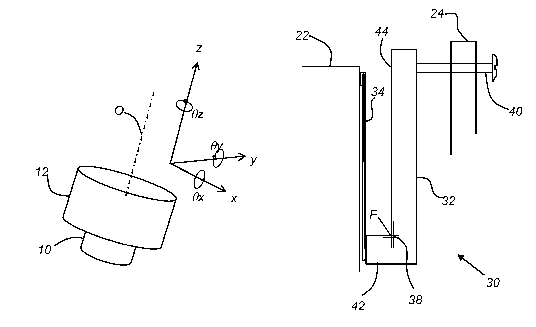
[0028]In the context of the present disclosure, terms “top” and “bottom” are relative and do not necessarily indicate any necessary orientation of a surface, but are used simply to refer to and distinguish opposite surfaces for a component or block of material.

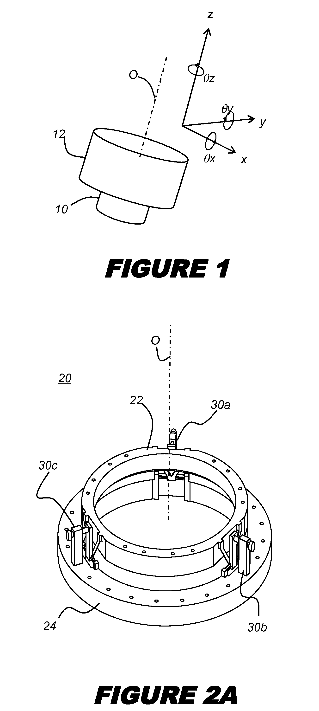
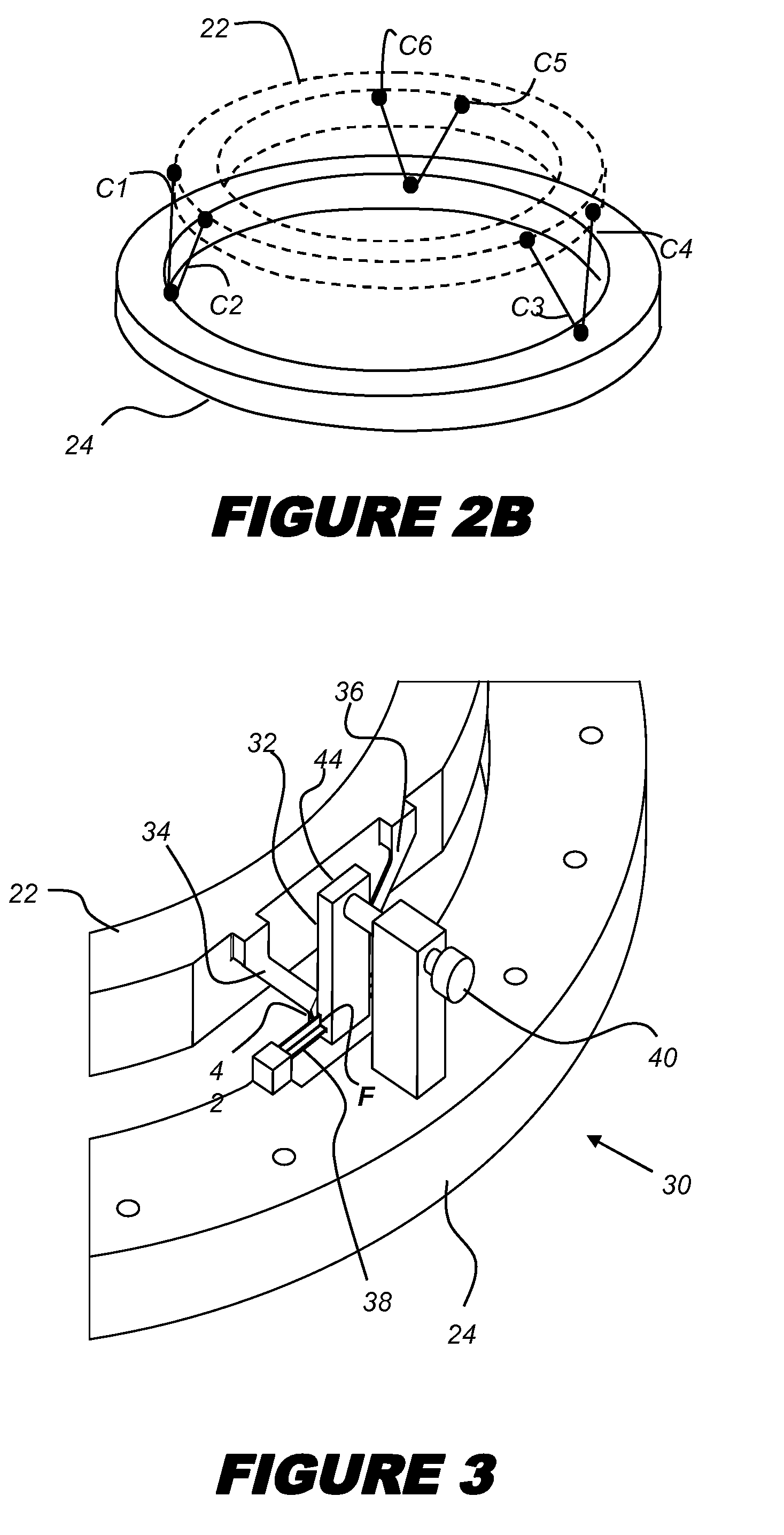
[0029]Figures shown and described herein are provided in order to illustrate key principles of operation and fabrication for optical mount devices according to the present invention and are not drawn with intent to show actual size or scale. Some exaggeration may be necessary in order to emphasize basic structural relationships or principles of operation.

[0030]It should be noted that the mathematical definition of a cylinder includes not only the familiar right circular cylinder, but also any number of other shapes whose outer surface can be defined by moving a straight line parallel to a fixed straight line, wherein the moving straight line intersects a fixed planar closed curve or base. Although cylindrical shapes are shown ...


PUM


Abstract

A positioning apparatus for providing relative movement between a first member and a second member has a lever element pivotably coupled to the first member along a fulcrum member and has an actuator arm and a positioner arm. First and second flexure elements extend between the positioner arm of the lever element and the second member. An actuator is coupled to the actuator arm of the lever element.

Description

CROSS-REFERENCE TO RELATED APPLICATIONS[0001]This application claims the benefit of priority under 35 U.S.C. §119(e) of U.S. Provisional Application Ser. No. 61 / 067,791 filed on Feb. 29, 2008.FIELD[0002]This invention generally relates to component mounting and more particularly relates to a mount for an optical element that allows positioning along an optical axis, but constrains rotational movement along any axis and constrains translational movement in directions orthogonal to the optical axis.BACKGROUND[0003]Photolithography or microlithography apparatus are widely used in the fabrication of microelectronic semiconductor devices and other microdevices. In photolithography, an optical system directs light energy to record a pattern at high resolution and with precise registration onto a photosensitive layer formed on a silicon wafer or other substrate. Continuing improvements in miniaturization place increasingly more challenging demands on the performance and accuracy of the opt...

Claims


Application Information

Patent Timeline
Patent Type & Authority Patents(United States)
IPC IPC(8): G02B7/02
CPCG03F7/70825G02B7/023B33Y80/00
Inventor BLANDING, DOUGLASS LBRUNING, JOHN HFRANKOVICH, JACK WHANFORD, KEITH EMAGIERSKI, KEVIN J
Owner CORNING INC
Why Eureka
Try Eureka