System and method for rapid isothermal gas expansion and compression for energy storage

a technology of isothermal gas and energy storage, applied in the direction of fluid couplings, servomotors, hybrid vehicles, etc., can solve the problem of system capital cos

Inactive Publication Date: 2010-09-28
SUSTAINX
View PDF283 Cites 109 Cited by
  • Summary
  • Abstract
  • Description
  • Claims
  • Application Information

AI Technical Summary

Benefits of technology

[0013]The invention overcomes the disadvantages of the prior art by providing systems and methods for rapidly and isothermally expanding gas in a cylinder, which can be a hydraulic / pneumatic converter component in a staged energy storage system that can store high-pressure gas at, for example, over 200 atmospheres (3000 PSI) for use by the system. A pressure vessel or cylinder defining a gas chamber (pneumatic side) and a fluid chamber (hydraulic side) has a piston or other mechanism, which separates the gas chamber and fluid chamber, preventing gas or fluid migration from one chamber to the next, while allowing the transfer of force / pressure between each opposing chamber. Both the gas chamber and the fluid chamber have primary ports that interface with the respective pneumatic and hydraulic components of the overall energy storage and recovery system.
[0014]The gas chamber / pneumatic side of the cylinder has additional ports. The additional gas exit port is in fluid communication with an input to a circulation device (for example, a pneumatic pump or fan impeller), the exit of which is in fluid communication with the gas input of a heat exchanger. The gas exit port of the heat exchanger is in fluid connection with the additional gas chamber input port. The heat exchanger has corresponding fluid ports that support a flow of ambient temperature fluid through the heat exchanger in a direction counter to the flow of gas in the heat exchanger. Thus, due to the heat exchange with the flowing fluid, the gas exiting the heat exchanger is returned to the gas chamber at ambient or near ambient temperature. The circulation of gas in the gas chamber through the heat transfer subsystem thereby maintains the gas in the gas chamber at ambient or near-ambient temperature. The entire gas circuit in the heat exchanger is sealed and capable of handling high pressures (for example, up to at least 200 atmospheres) encountered within the pneumatic side of the cylinder. The fluid side of the heat exchanger communicates with an appropriate reservoir of ambient fluid. This reservoir can be an open source, such as a large body or water, a cooling tower or a ground source exchange loop. Notably, the systems and methods of the invention can be implemented using commercially available hydraulic / pneumatic cylinders and intensifiers, and the heat exchanger can likewise, be constructed from commercially available, high-pressure-handling components, thereby reducing the cost and complexity of the overall system. Since the heat exchanger is external of the hydraulic / pneumatic cylinder, it can be located anywhere that is convenient and can be sized as needed to deliver a high rate of heat exchange. In addition, the heat transfer subsystem can be attached to the cylinder with conventional plumbing components / fittings.
[0015]Generally, the per-kW capital cost of the system is directly related to the power capacity of the system, which in turn is related to the heat transfer rate. Achieving higher heat transfer rates allows for increased power output for a given desired efficiency. Thus, the heat transfer rate is indirectly related to the capital cost of the system. For example, if the power output is increased by a factor of 4, the system cost ($ / kW) is reduced by a factor of 4. Heat transfer can be improved by two primary techniques: increasing the air flow rate through the heat exchanger and increasing the heat transfer area.
[0023]In various embodiments of the method, the gas is circulated through a heat transfer subsystem in fluid communication with the pneumatic side of the hydraulic cylinder. The method can include the step of controlling the circulation of the gas through the heat transfer system based on a temperature of at least one of the gas in the pneumatic side of the hydraulic cylinder, ambient air proximate the heat transfer subsystem, or the gas exiting the heat transfer subsystem. In addition, the heat transfer subsystem can remove heat from the gas when compressing the gas and add heat to the gas when expanding the gas.

Problems solved by technology

Thus, the heat transfer rate is indirectly related to the capital cost of the system.

Method used


Image

  • System and method for rapid isothermal gas expansion and compression for energy storage
  • System and method for rapid isothermal gas expansion and compression for energy storage
  • System and method for rapid isothermal gas expansion and compression for energy storage

Examples


Embodiment Construction

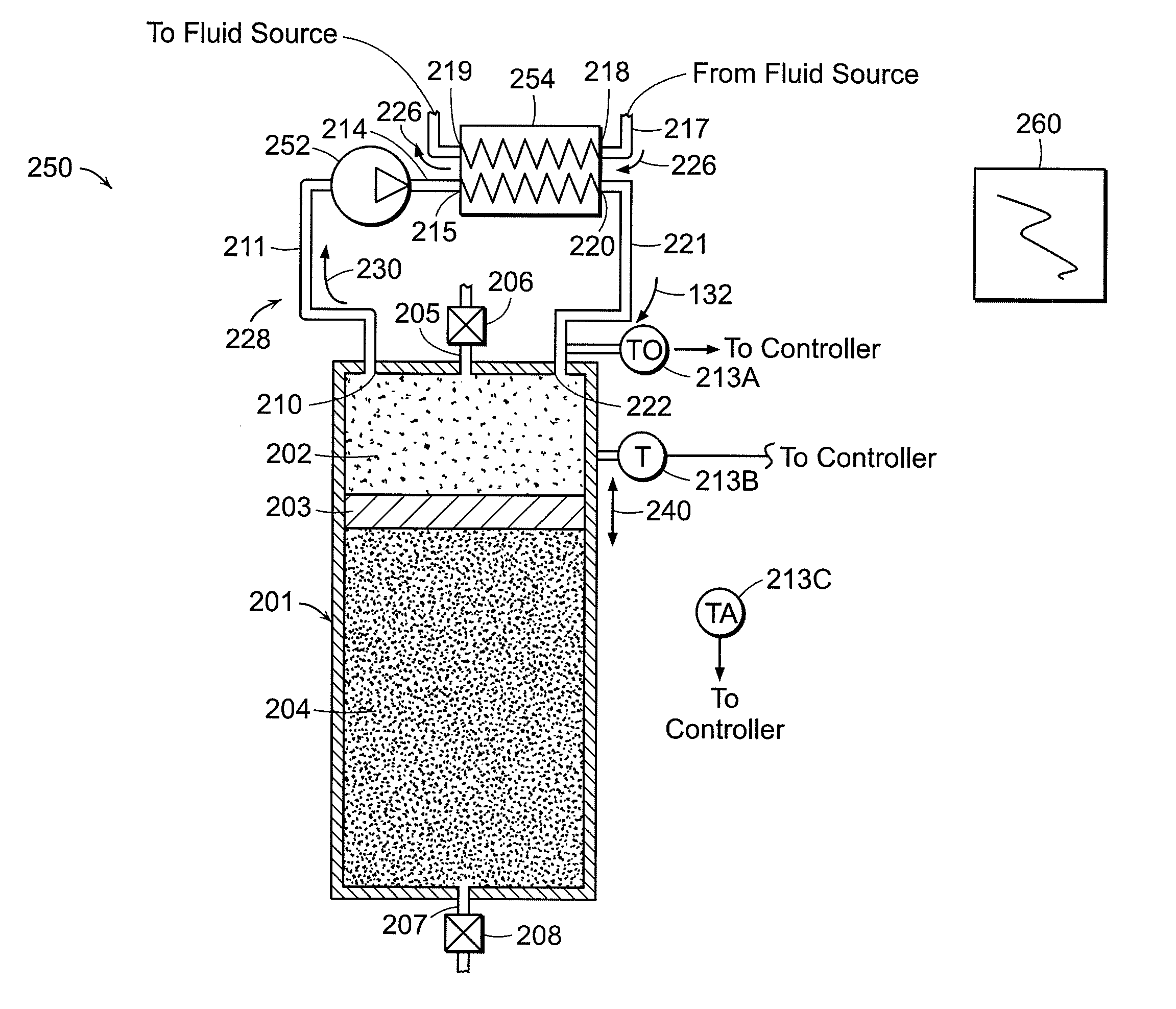
[0035]In the following, various embodiments of the present invention are generally described with reference to a single hydraulic cylinder (for example, an accumulator or an intensifier) and simplified valve arrangements. It is, however, to be understood that the present invention can include any number and combination of accumulators, intensifiers, and valve arrangements. In addition, any dimensional values given are exemplary only, as the systems according to the invention are scalable and customizable to suit a particular application. Furthermore, the terms pneumatic, gas, and air are used interchangeably and the terms hydraulic and fluid are also used interchangeably.

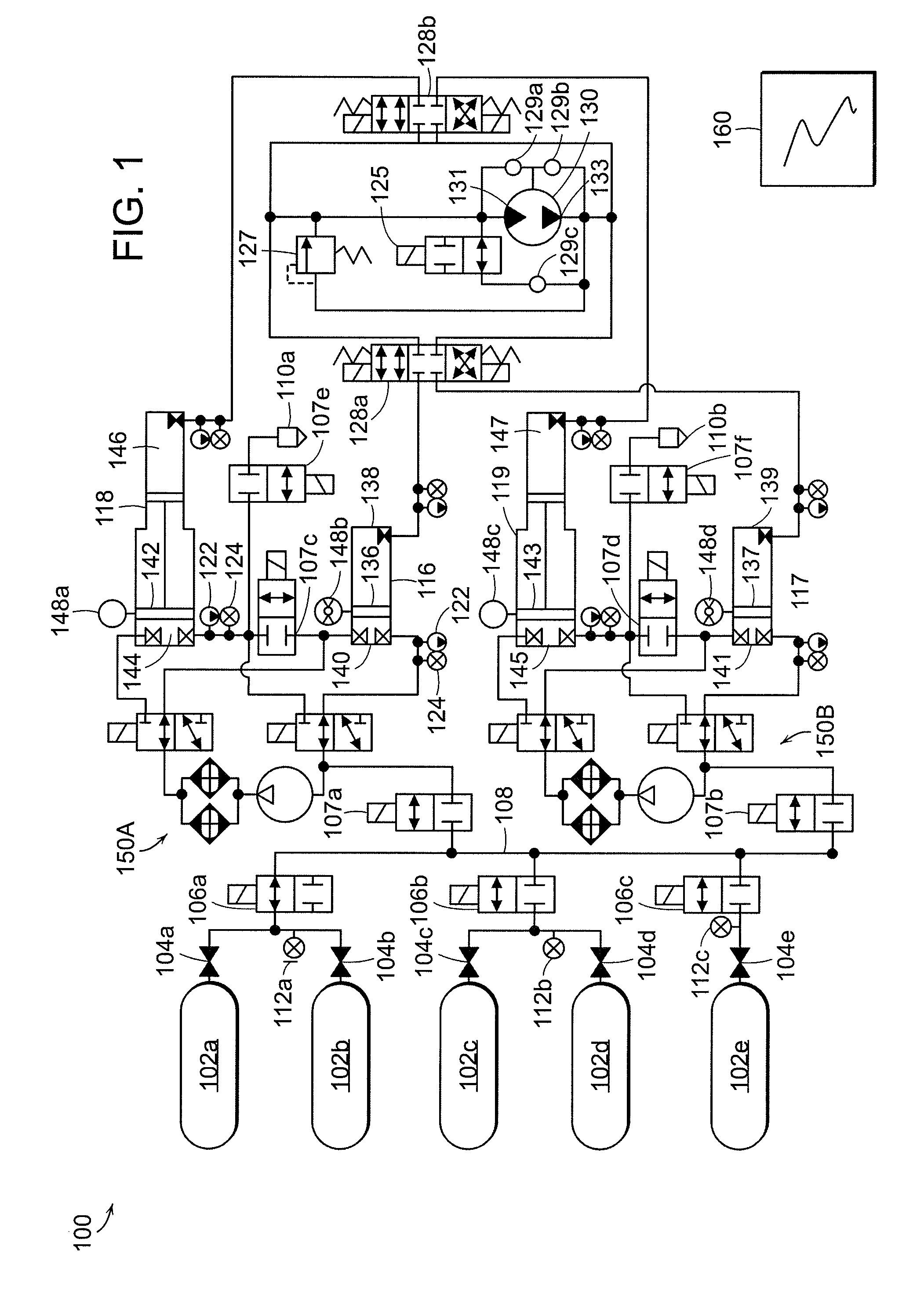
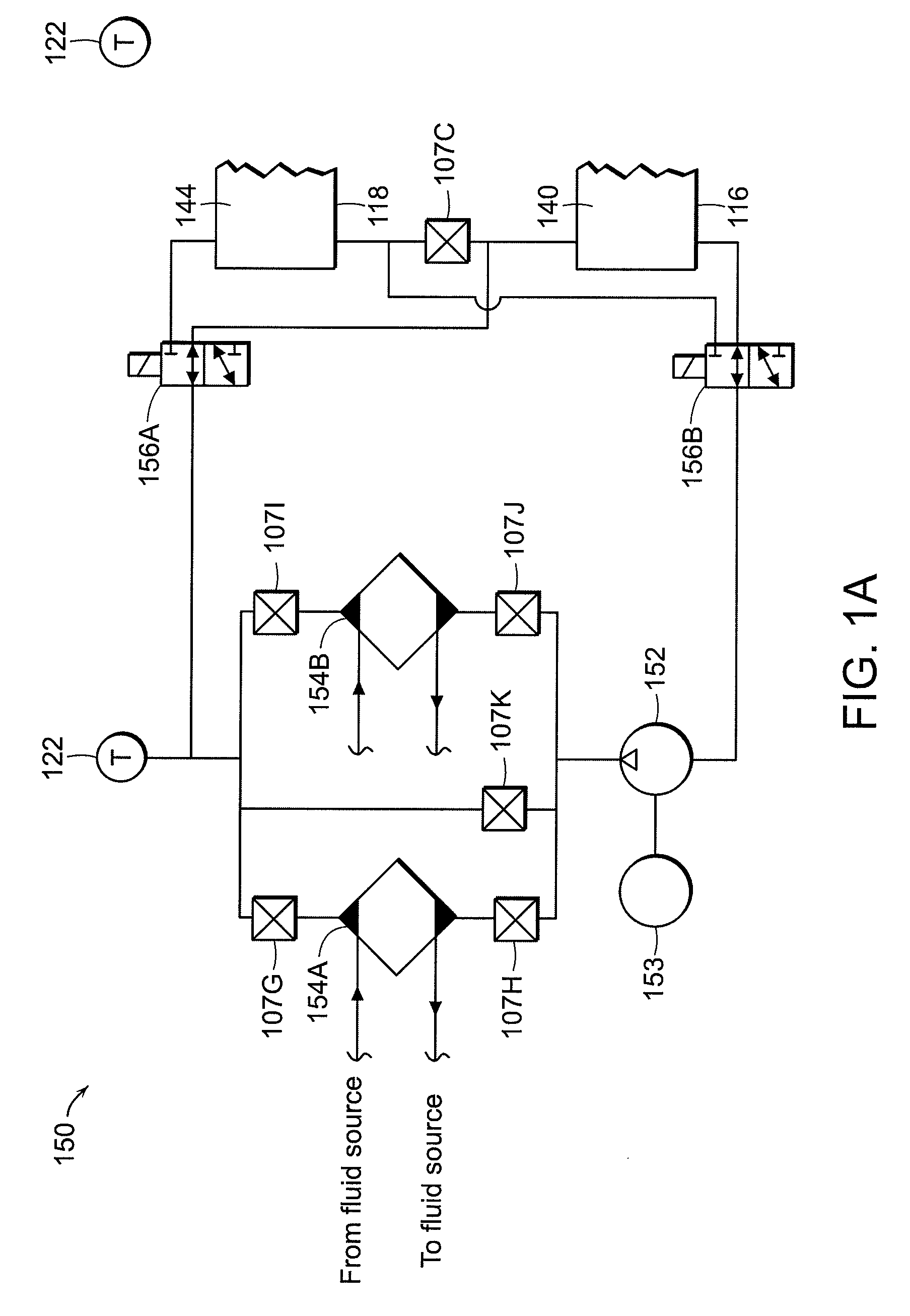
[0036]FIG. 1 depicts generally a staged hydraulic-pneumatic energy conversion system that stores and recovers electrical energy using thermally conditioned compressed fluids and incorporates various embodiments of the invention. Various types of staged hydraulic-pneumatic energy conversion systems that store and rec...


PUM


Abstract

The invention relates to systems and methods for rapidly and isothermally expanding gas in a cylinder. The cylinder is used in a staged hydraulic-pneumatic energy conversion system and includes a gas chamber (pneumatic side) and a fluid chamber (hydraulic side) and a piston or other mechanism that separates the gas chamber and fluid chamber while allowing the transfer of force / pressure between each opposing chamber. The gas chamber of the cylinder includes ports that are coupled to a heat transfer subassembly that circulates gas from the pneumatic side and exchanges its heat with a counter flow of ambient temperature fluid from a reservoir or other source.

Description

CROSS-REFERENCE TO RELATED APPLICATIONS[0001]This application claims priority to U.S. Provisional Patent Application Ser. No. 61 / 059,964, filed on Jun. 9, 2008, the disclosure of which is hereby incorporated herein by reference in its entirety.STATEMENT REGARDING FEDERALLY SPONSORED RESEARCH[0002]This invention was made with government support under IIP-0810590 awarded by the NSF. The government has certain rights in the invention.FIELD OF THE INVENTION[0003]This invention relates to systems and methods for storing and recovering electrical energy using compressed gas, and more particularly to systems and methods for improving such systems and methods by rapid isothermal expansion and compression of the gas.BACKGROUND OF THE INVENTION[0004]As the world's demand for electric energy increases, the existing power grid is being taxed beyond its ability to serve this demand continuously. In certain parts of the United States, inability to meet peak demand has led to inadvertent brownouts...

Claims


Application Information

Patent Timeline
Patent Type & Authority Patents(United States)
IPC IPC(8): F02G1/04F16D31/02F01K25/02F02C1/04B66F7/18F15B11/072
CPCH02J15/006F01K27/00F15B11/0725Y02E60/15B60K6/12B60Y2400/14Y02T10/6208F15B2201/42Y02T10/62Y02E60/16
Inventor BOLLINGER, BENJAMIN R.
Owner SUSTAINX
Why Eureka
Try Eureka