Trigger wire system

a trigger wire and wire technology, applied in the field of prosthesis deployment, can solve the problems of inaccurate deployment, jamming or breaking of the trigger wire, etc., and achieve the effect of preventing the fouling of the trigger wir

Inactive Publication Date: 2010-09-28
WILLIAM A COOK AUSTRALIA +1
View PDF12 Cites 109 Cited by
  • Summary
  • Abstract
  • Description
  • Claims
  • Application Information

AI Technical Summary

Benefits of technology

[0012]Preferably the trigger wires are formed from stainless steel or other metal coated with polytetrafluoroethylene to provide a wire that will move easily.
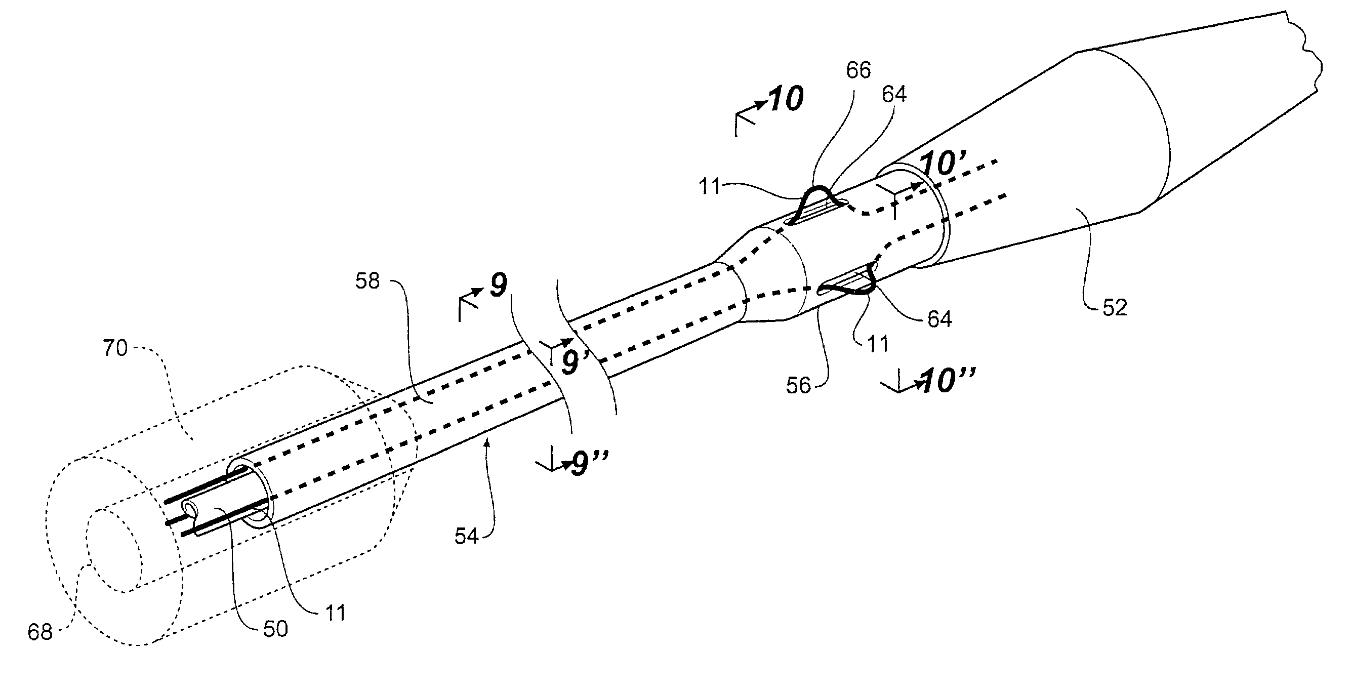
[0017]In an alternative form the invention may be said to reside in a trigger wire guide for a prosthesis deployment device, the prosthesis deployment device being of a type having a proximal end extending to a proximal nose cone dilator and having a trigger wire or wires and trigger wire release mechanism adapted to retain the proximal end of a prosthesis adjacent the nose cone dilator, characterized by a trigger wire guiding means to retain the trigger wire or wires to prevent fouling of the trigger wire with the prosthesis when the prosthesis is carried on the deployment device.

Problems solved by technology

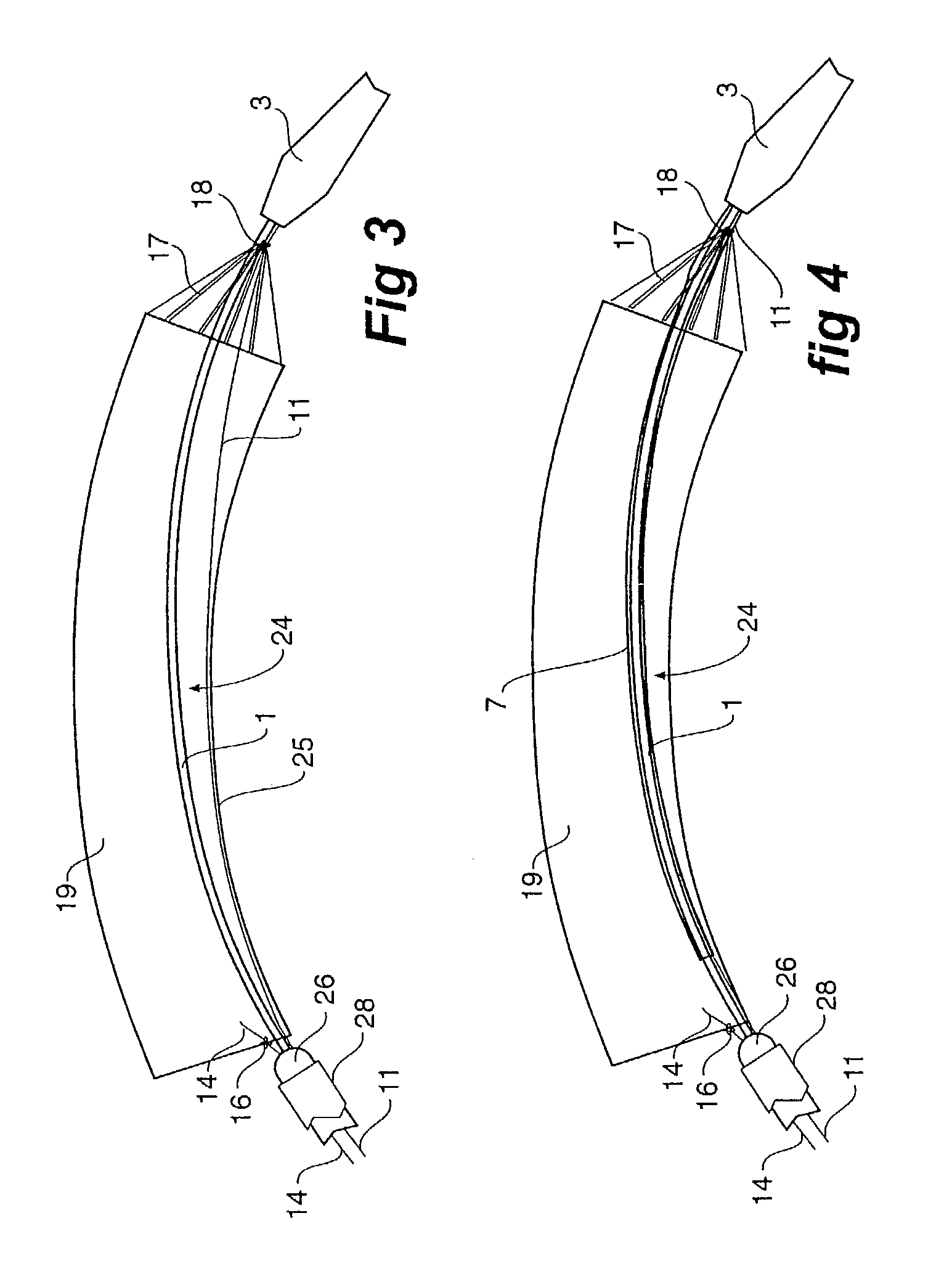
In the region of the deployment device in which the prosthesis is carried, trigger wires can foul or catch with stents on the deployment device, particularly when the deployment device is bent to pass through convolutions in the lumen, therefore causing inaccurate deployment and perhaps jamming or breakage of the trigger wire.

Method used


Image

  • Trigger wire system
  • Trigger wire system
  • Trigger wire system

Examples


Embodiment Construction

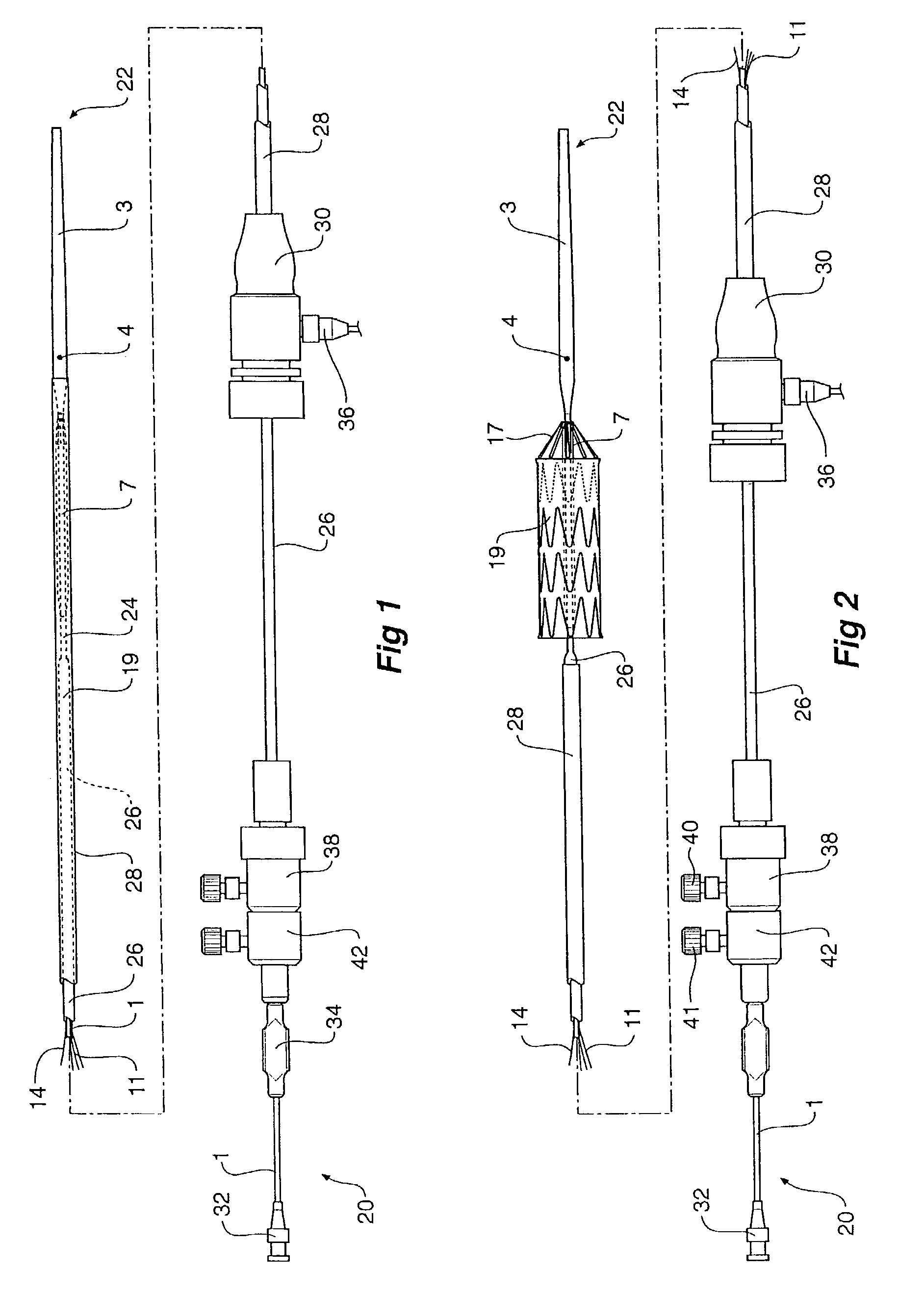
[0044]Now looking more closely to the drawings and in particular the embodiment shown in FIGS. 1 and 2 there is shown a prosthesis deployment device upon which the trigger wire guide of the present invention may be used.

[0045]The prosthesis deployment device of this invention comprises a guide wire catheter 1 extending between a distal end 20 and a proximal end 22 of the deployment device. In use the distal end 20 is adapted to remain outside the body of a patient and the proximal end 22 with its nose cone dilator 3 is adapted in use to be inserted into the arteries of a patient such as for treatment of an aortic aneurism. For such a treatment the deployment device is inserted through an incision into the femoral artery and through the iliac arteries to the aorta. The deployment device is usually deployed over a guide wire (not shown). There is a recess 24 between the nose cone dilator 3 and catheter body 26. The recess 24 is adapted to retain a prosthesis 19 in a compressed state w...


PUM


Abstract

A trigger wire guide for a prosthesis deployment device. The prosthesis deployment device has a proximal end extending to a proximal nose cone dilator and having a trigger wire or wires and trigger wire release mechanism to retain the proximal end of a prosthesis adjacent the nose cone dilator. The trigger wire guide retains the trigger wire or wires to prevent fouling of the trigger wire with a prosthesis when the prosthesis is carried on the deployment device. The guide can be crimped or soldered to a guide wire catheter or concentric with it.

Description

CROSS-REFERENCE TO RELATED APPLICATIONS[0001]This application claims priority to U.S. provisional application Ser. No. 60 / 392,682, filed Jun. 28, 2002, and of the same title. This application also claims priority to U.S. provisional application Ser. No. 60 / 384,056, filed May 29, 2002, entitled “Multi-Piece Prosthesis Deployment Apparatus, which is incorporated by reference herein in its entirety.TECHNICAL FIELD[0002]This invention relates to a prosthesis deployment and more particularly to a trigger wire arrangement used on such devices to release a prosthesis when it is in a body lumen.BACKGROUND OF THE INVENTION[0003]Deployment devices are used to deploy prostheses and in particular prostheses incorporating self expanding stents within lumens in the human body. This invention will generally be discussed in relation to the deployment of prostheses within the aorta but the invention is not so limited and may be used for other of deployment sites as well.[0004]In some forms of deploy...

Claims


Application Information

Patent Timeline
Patent Type & Authority Patents(United States)
IPC IPC(8): A61F2/06A61F2/84A61F2/82A61M25/00A61M25/09
CPCA61F2/95A61F2/966A61M25/00A61F2002/9511A61F2002/9665A61M2025/0096
Inventor HARTLEY, DAVID ERNESTMILLS, EDWARD GRAHAMRASMUSSEN, ERIK EDELBOESCHULTZ, JENS VEJBY
Owner WILLIAM A COOK AUSTRALIA
Why Eureka
Try Eureka