Arrangement in an electrical machine

a technology of electrical machines and rotors, applied in the direction of emergency protective circuit arrangements, instruments, associations for rectification, etc., can solve the problems of affecting the operating characteristics of the machine, direct or indirect damage to the machine's components, and the rotor position may deviate from the centre line of the machin

Inactive Publication Date: 2010-09-28
ABB (SCHWEIZ) AG
View PDF28 Cites 4 Cited by
  • Summary
  • Abstract
  • Description
  • Claims
  • Application Information

AI Technical Summary

Benefits of technology

[0015]According to a preferred embodiment, the means of supervision is connected in series with another supervis

Problems solved by technology

Extra particles may affect the operating characteristics of the machine, such as noise and cooling, and may also cause direct or indirect damage to the machine's components.
The rotor position may dev

Method used


Image

  • Arrangement in an electrical machine
  • Arrangement in an electrical machine
  • Arrangement in an electrical machine

Examples


Embodiment Construction

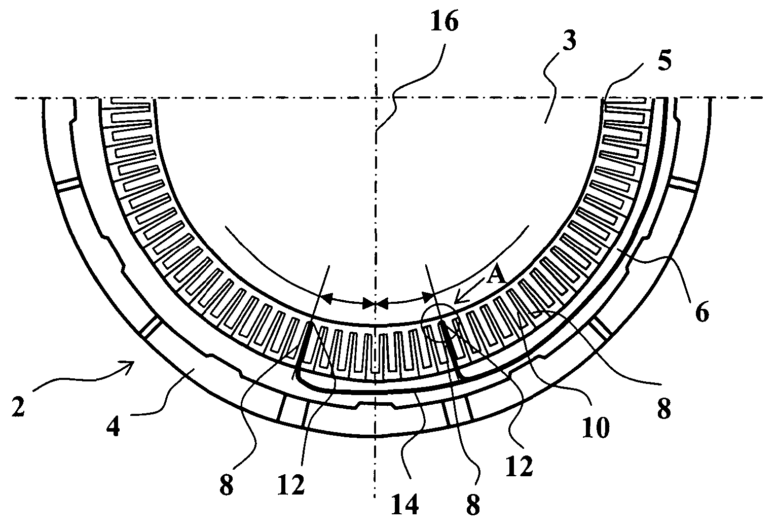
[0021]FIG. 1 is a cross-section of the lower half of an electrical machine. The stator 2 is supported in a horizontal position, and the rotor 3 is installed with an air gap 5 between the stator and rotor. The stator sheet pack 6 is attached to the stator body 4. The stator sheet pack forms stator teeth 8 protruding towards the machine's air gap and stator grooves 10 between the teeth, opening towards the air gap. With regard to the implementation of the invention, the grooves can also be half-open or completely closed. The windings to be fitted into the grooves are not illustrated and can be implemented by generally known methods upon application of the invention.

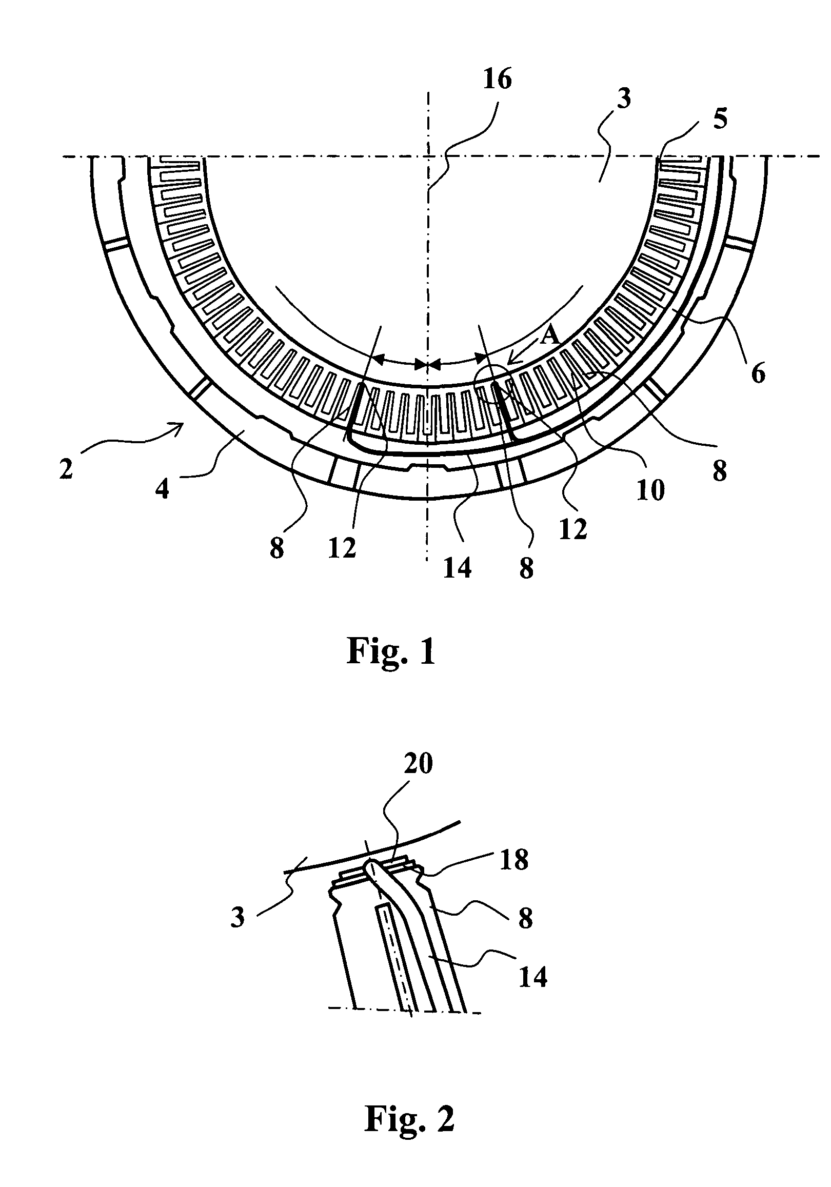
[0022]When the machine is installed horizontally, a means of supervision 12 is fitted to the positions of the two teeth 8 in the lower section of the stator 2 and, preferably, extends over the entire length of the stator in the axial direction of the machine. The surface of the means of supervision 12 slightly protrudes fro...


PUM


Abstract

The invention relates to an arrangement for indicating a fault in an electrical machine having a stator and a rotor with an air gap between it and the stator. In order to detect impurities or similar objects entering the air gap, a means of supervision is arranged on the stator surface facing the rotor. The means of supervision is at least partially protruding from the stator surface, and the integrity of the included detection element, such as a copper wire, is established using a supervision circuit connected to the detection element.

Description

RELATED APPLICATIONS[0001]This application claims priority under 35 U.S.C. §119 Finish Application 20041098 filed in Finland on Aug. 19, 2004 and is a US national phase application of PCT / FI2005 / 000348 filed as an International Application on Jul. 29, 2005 designating the U.S., the entire contents of which are hereby incorporated by reference in their entireties.TECHNICAL FIELD[0002]An arrangement for indicating failure in an electrical machine is disclosed.BACKGROUND INFORMATION[0003]In an electrical machine the rotor rotates with an air gap between it and the stator. The rotor is most often fitted inside the stator, but solutions also exist in which the rotor is external to the stator or fitted with an air gap between it and the stator in the axial direction. The present invention is applicable to many different types of machines.[0004]To the greatest extent possible, the air gap in the machine must be free of any dust and dirt coming from outside the machine and any impurities cr...

Claims


Application Information

Patent Timeline
IPC IPC(8): H02K11/00H02K23/66G01R31/02G01R31/28G01R31/34
CPCG01R31/2829H02K11/001G01R31/026G01R31/34H02K11/20G01R31/343G01R35/00H02K11/00G01R31/50
Inventor OLKANEN, KARIIISAKKALA, JARKKOJAPPINEN, JARI
Owner ABB (SCHWEIZ) AG
Why Eureka
Try Eureka