

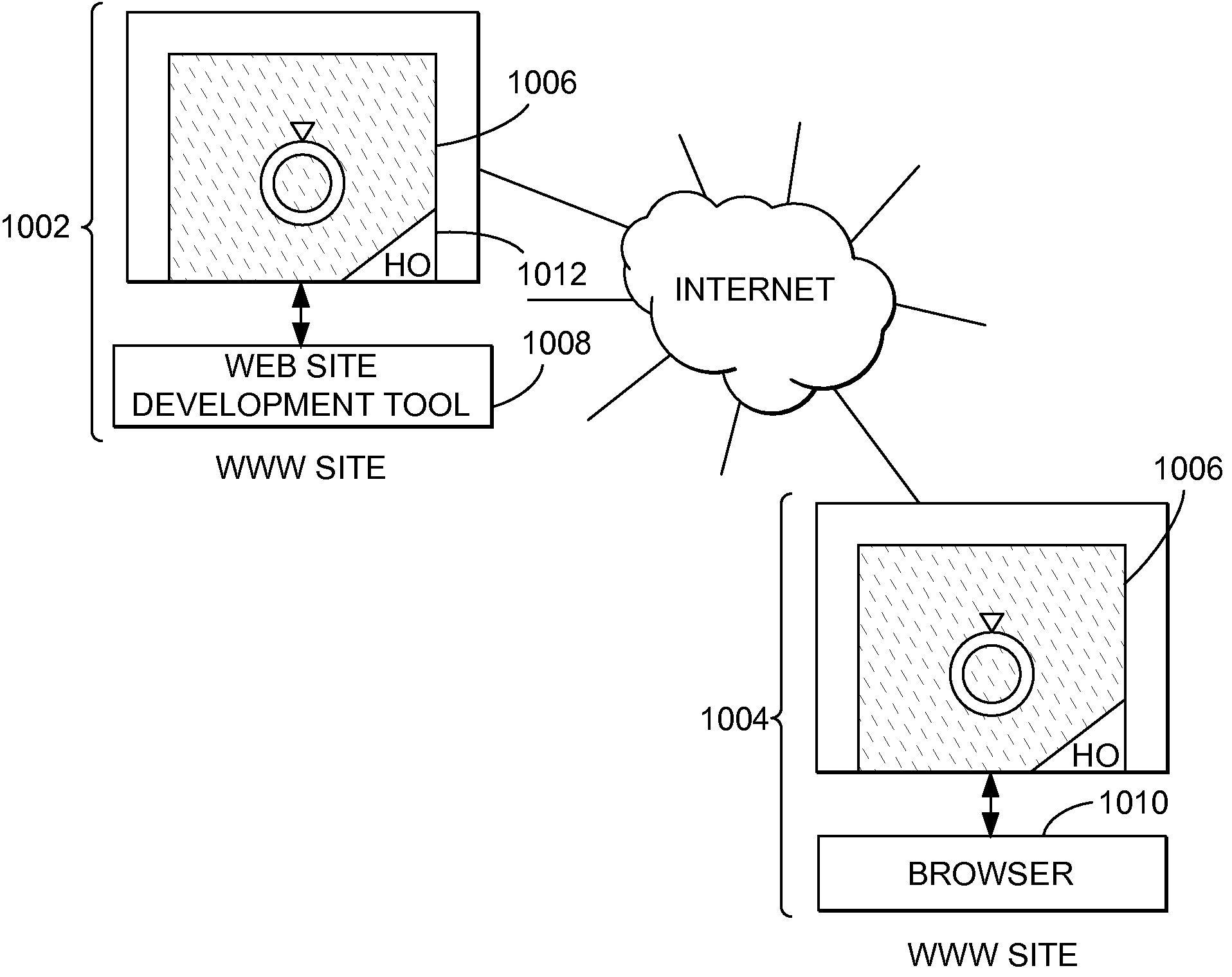
Network linking methods and apparatus
a network linking and network technology, applied in the field of computer network navigation, can solve the problems of no simple means of tracing the path to the original purchaser of the material, no commercial value compromise, and historical problems compounded, so as to achieve the effect of maximizing the signal energy of identification, maximizing the value of identification, and avoiding historical problems
- Summary
- Abstract
- Description
- Claims
- Application Information
AI Technical Summary
Benefits of technology
Problems solved by technology
Method used
Image

Examples
specific example
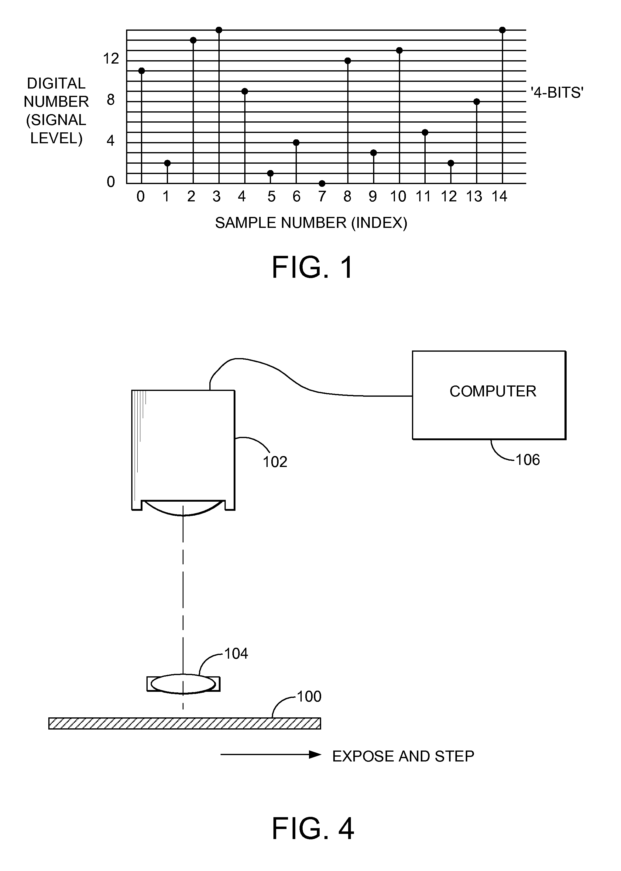
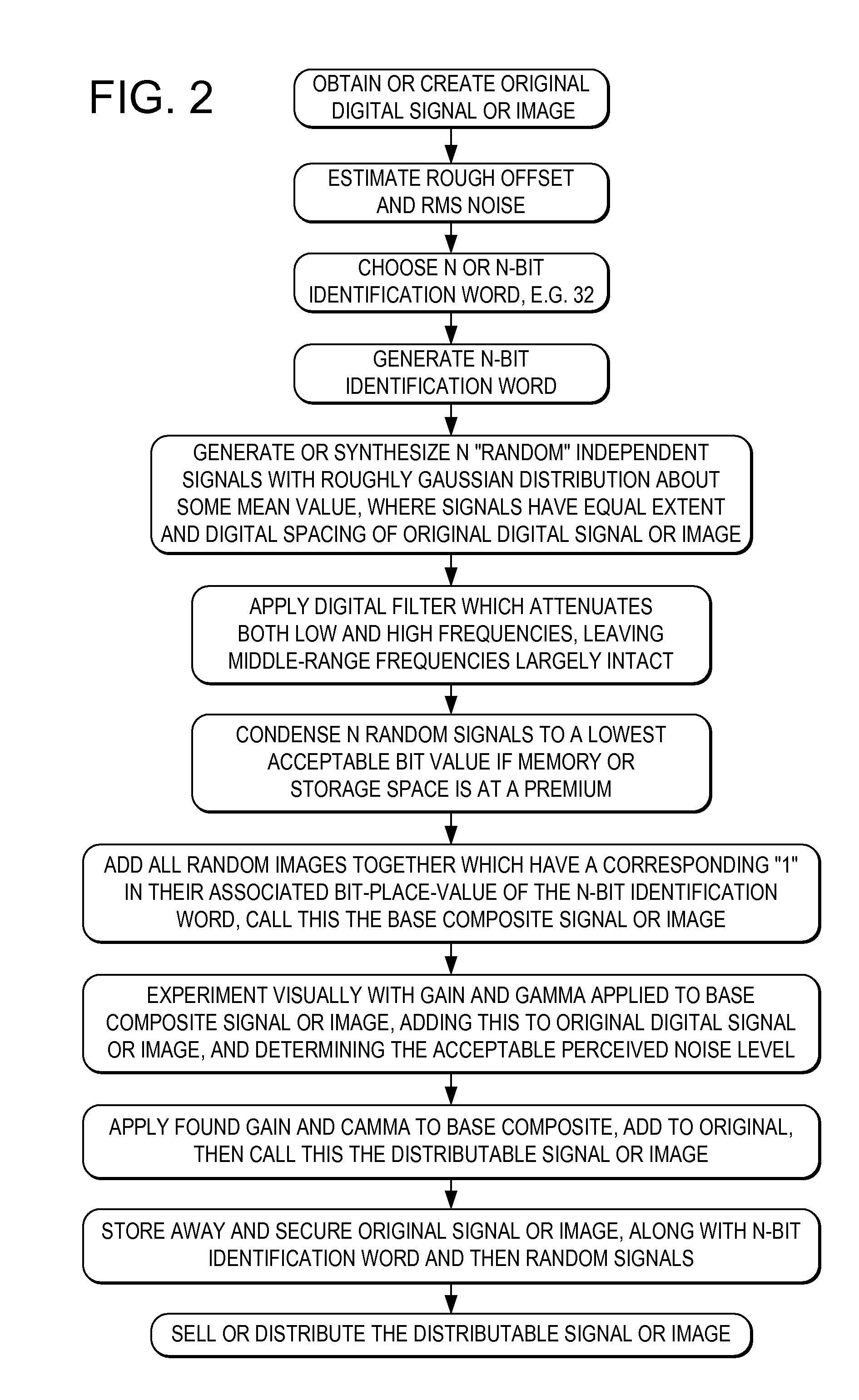
[0069]Imagine that we have taken a valuable picture of two heads of state at a cocktail party, pictures which are sure to earn some reasonable fee in the commercial market. We desire to sell this picture and ensure that it is not used in an unauthorized or uncompensated manner. This and the following steps are summarized in FIG. 2.
[0070]Assume the picture is transformed into a positive color print. We first scan this into a digitized form via a normal high quality black and white scanner with a typical photometric spectral response curve. (It is possible to get better ultimate signal to noise ratios by scanning in each of the three primary colors of the color image, but this nuance is not central to describing the basic process.)
[0071]Let us assume that the scanned image now becomes a 4000 by 4000 pixel monochrome digital image with a grey scale accuracy defined by 12-bit grey values or 4096 allowed levels. We will call this the “original digital image” realizing that this is the sa...
PUM
 Abstract
Description
Claims
Application Information