Inertia driven eye protection for a scope

a technology of eye protection and lens, applied in the field of optical devices, can solve the problems of not being able to directly touch the scope should not be placed directly against the eye of a shooter, and the expense of eye relief, so as to reduce the likelihood, shorten the scope length, and increase the eye clearance

Inactive Publication Date: 2010-10-05
BURRIS
View PDF28 Cites 4 Cited by
  • Summary
  • Abstract
  • Description
  • Claims
  • Application Information

AI Technical Summary

Benefits of technology

[0010]Embodiments of the present disclosure relate to a firearm scope having an ocular lens that retracts under recoil of a firearm. In effect, the retraction of the ocular lens shortens the length of the scope and temporarily increases eye clearance during recoil, thereby reducing the likelihood that the scope will come into contact with a shooter's face during recoil of the firearm. The retractable ocular lens has a secondary benefit of cushioning impact should the scope make contact with the face.
[0011]Another embodiment of the present disclosure is an eyepiece apparatus for use with existing scopes. The eyepiece includes a shock mount and a spring-biased ocular lens system that retracts due to recoil of a firearm, thereby effectively increasing eye clearance during the peak recoil acceleration. The spring-biased ocular lens system is also capable of retraction upon contact with the shooter's face to cushion any impact if the shooter is unable to handle the rearward momentum of a firearm.

Problems solved by technology

The rearmost portion of this adjustable ocular lens mount is frequently cushioned and commonly referred to as an “eyecup.” However, unlike other optical systems (e.g., telescopes or binoculars), a firearm scope should not be placed directly against a shooter's eye due to the risk of injury resulting from recoil.
Hunters often place a premium on both field of view and magnification, frequently at the expense of eye relief.
Given the competing requirements noted above, firearm scope designs are a compromise that yield less than ideal eye clearance in some situations.
Consequently, a recurrent problem experienced by firearm scope users is an injury to the eye area induced by impact of the eyecup with the shooter's face during recoil.
Additionally, sufficient eye clearance obtained when a shooter holds the firearm comfortably with the head in a natural position may not be enough when a shot is taken while aiming uphill or on uneven ground.
Furthermore, even experienced shooters may suffer an injury when the recoil from an unfamiliar gun is greater than anticipated.
Indeed, the current trend toward more powerful firearms and cartridges has increased the incidence of bodily injury and thus there is a need for more eye clearance than current designs allow.
However, a common failing of such existing devices is that they add length to the rear end of the scope, thereby reducing eye clearance and placing the shooter's face closer to the eyecup which causes injury.
Therefore, prior art cushioning solutions compel the shooter to place the scope near enough the eye to be of concern, particularly on high recoil guns.

Method used


Image

  • Inertia driven eye protection for a scope
  • Inertia driven eye protection for a scope
  • Inertia driven eye protection for a scope

Examples


Embodiment Construction

[0021]This disclosure will now more fully describe exemplary embodiments with reference to the accompanying drawings, in which specific embodiments are shown. Other aspects may, however, be embodied in many different forms and the inclusion of specific embodiments in the disclosure should not be construed as limiting such aspects to the embodiments set forth herein. Rather, the embodiments depicted in the drawings are included to provide a disclosure that is thorough and complete and which fully conveys the intended scope to those skilled in the art. When referring to the figures, like structures and elements shown throughout are indicated with like reference numerals.

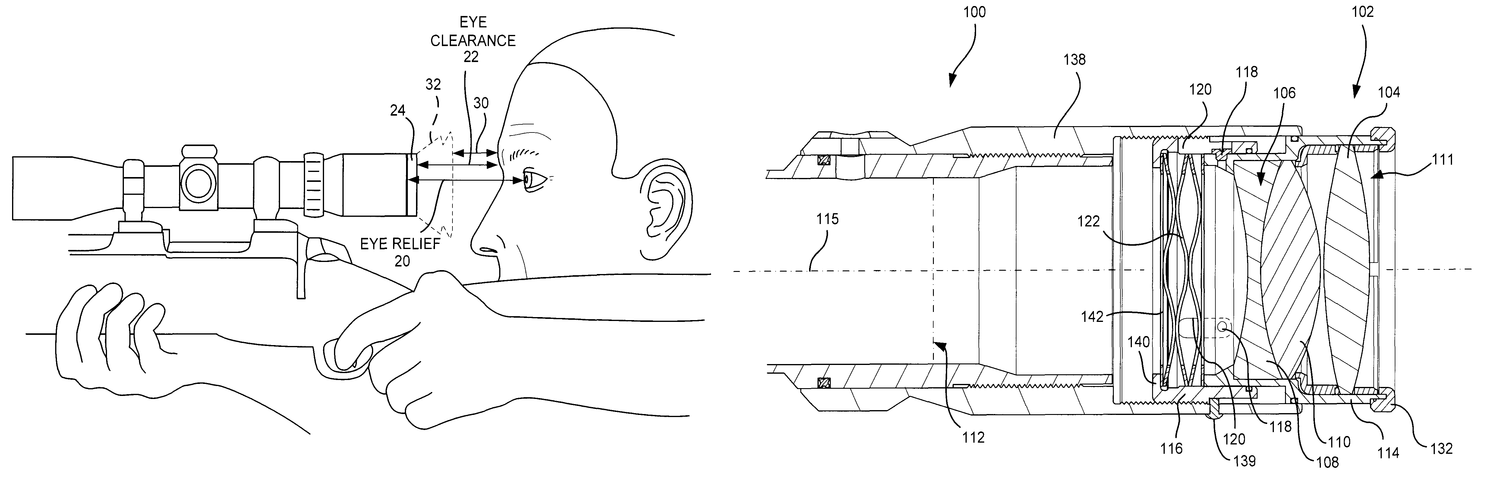
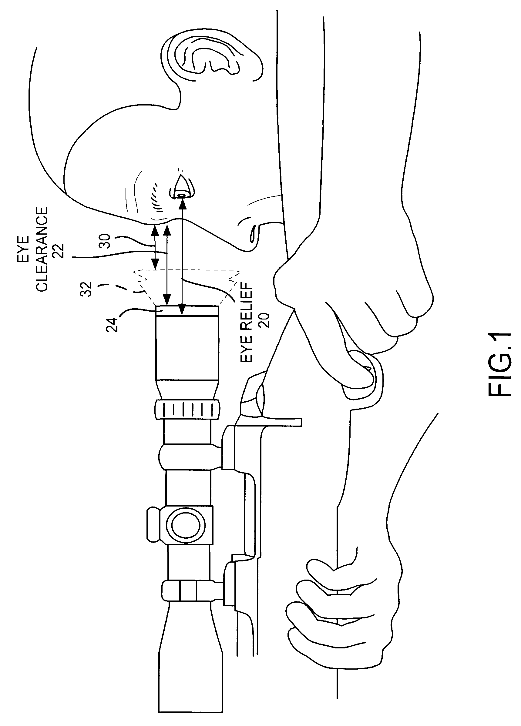
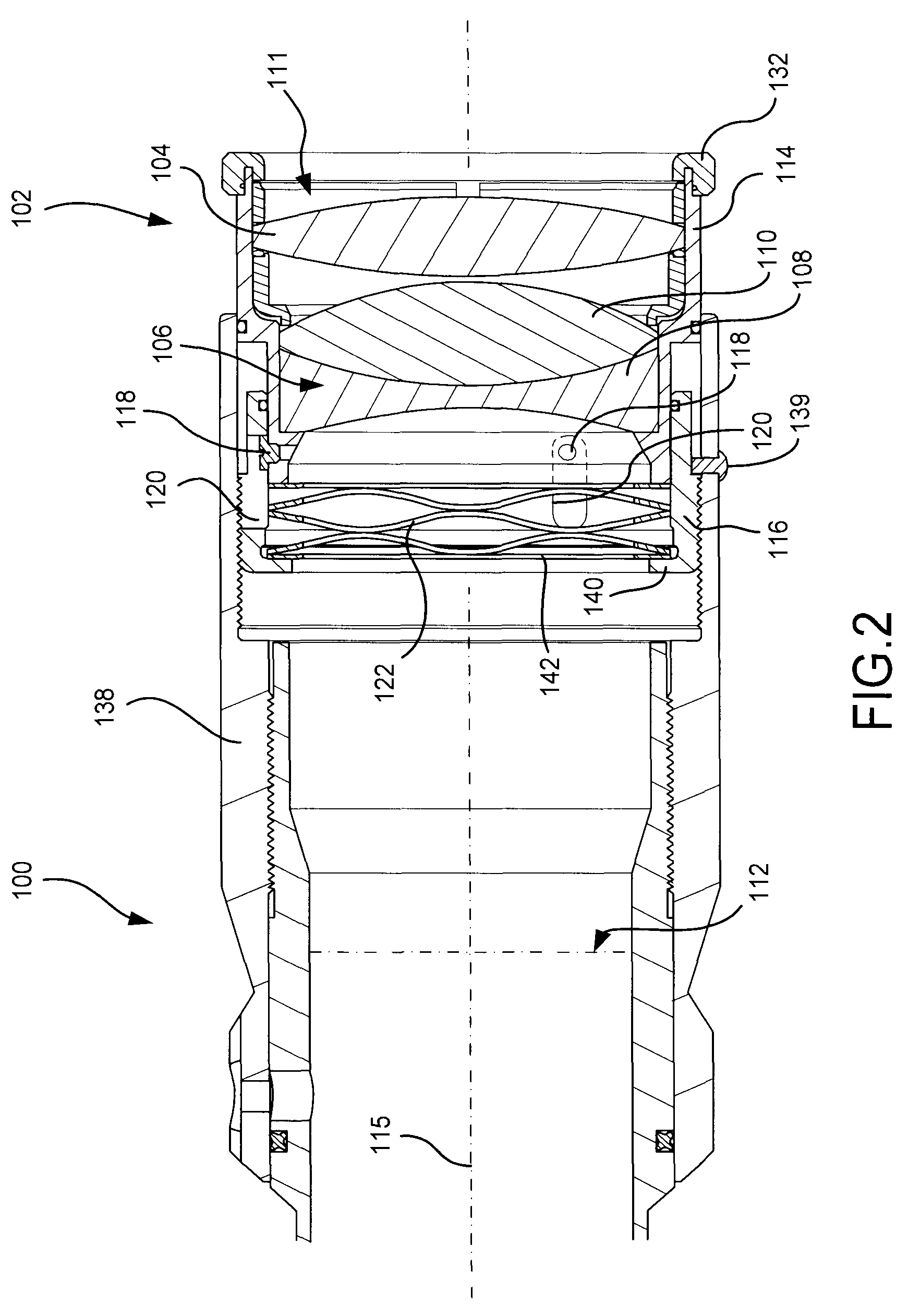
[0022]An optical firearm scope consists of a series of lenses mounted on a tubular structure. An objective lens system is located at the forward (or target) end of the scope, and an ocular lens system is located at the rear end of the scope. Both the objective lens system and the ocular lens system may consist of eithe...


PUM


Abstract

An eyepiece of a firearm scope includes a spring positioned between a shock mount and an ocular lens, wherein the spring holds the ocular lens a predetermined position from an objective lens of the scope when the spring is in an uncompressed state. During recoil of the firearm, the spring compresses to allow the ocular lens to travel towards the objective lens, thereby increasing an effective eye clearance distance between the ocular lens and a shooter. Following recoil, the spring expands to return the ocular lens to the predetermined position. The spring compresses again during impact of the eyepiece with the shooter's face, thereby partially absorbing the force of the impact and reducing the chance of injury to the shooter.

Description

TECHNICAL FIELD[0001]The invention relates generally to optical devices such as rifle scopes and, more particularly, to eye protection for such devices.BACKGROUND[0002]A firearm scope typically includes a series of lenses which produce an image of a target object inside the scope at multiple locations or “focal planes” within the scope. These lenses are positioned very precisely within a tubular structure that mounts atop a firearm. Scopes typically include a sighting aid which can be as simple as a cross hair reticle having two intersecting fibers mounted within a ring that is placed on a longitudinal axis of the tube. The cross hairs are located on one of the focal planes formed by the lenses so as to be superimposed on an image of the target.[0003]A shooter looks through one or more ocular lenses within an eyepiece at the rear of the scope, and it is this eyepiece that focuses and magnifies the final image for the shooter. Specifically, the position of the eyepiece or ocular lens...

Claims


Application Information

Patent Timeline
Patent Type & Authority Patents(United States)
IPC IPC(8): F41G1/38
CPCF41G1/38F41G1/383
Inventor MCCARTY, JOHN PAUL
Owner BURRIS
Why Eureka
Try Eureka