
Power tool with a slip clutch

a technology of power tools and slip clutches, applied in the field of power tools, can solve the problems of increasing manufacturing and assembly costs

Active Publication Date: 2010-10-05
HILTI AG
View PDF19 Cites 6 Cited by
  • Summary
  • Abstract
  • Description
  • Claims
  • Application Information

AI Technical Summary

Benefits of technology

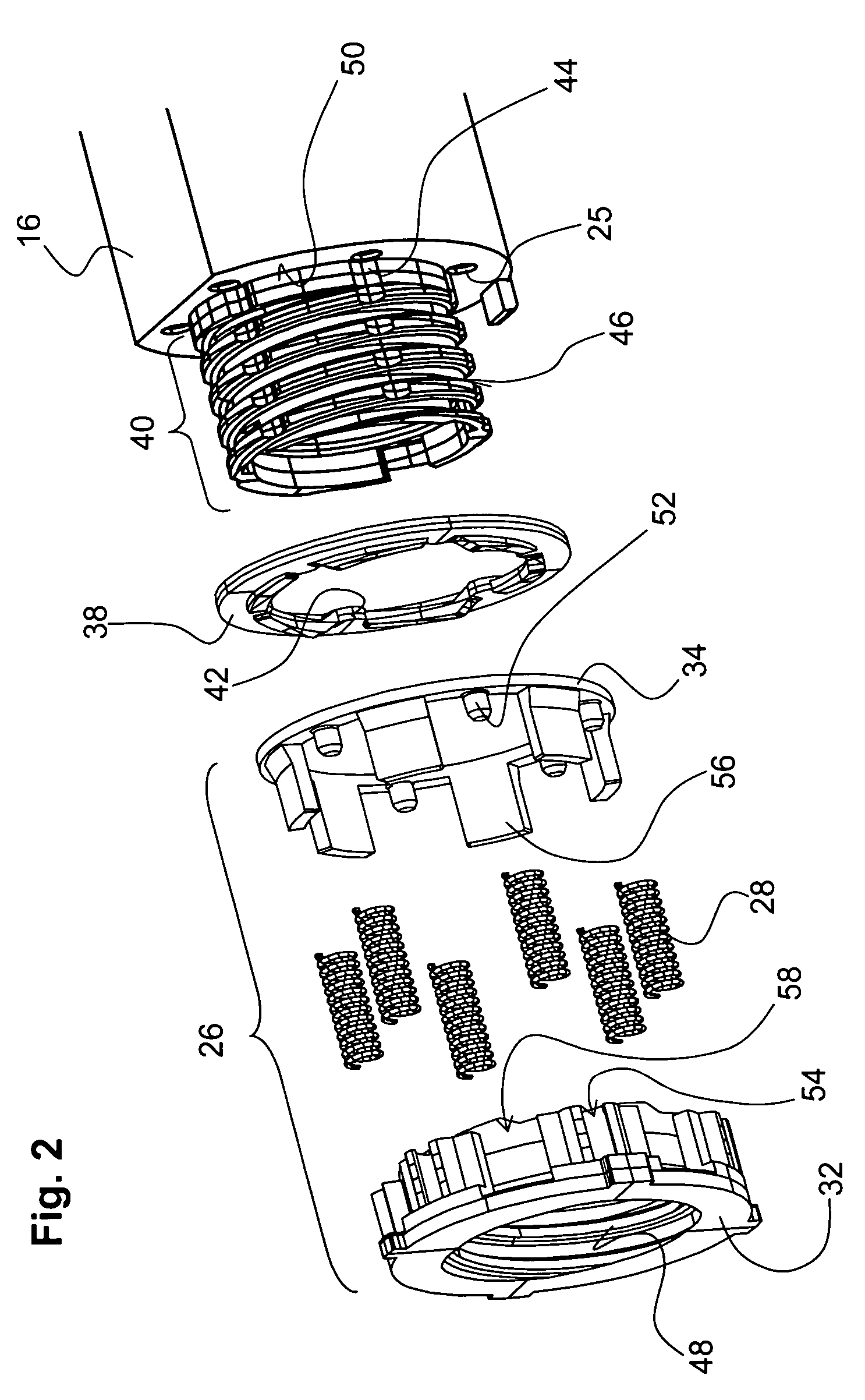
The present invention provides a power tool with a common support element for supporting spring elements and a movable adjustment element. This allows for easy assembly and adjustment of the spring elements without needing to assemble the entire power tool. The support element is formed as a guide frame rotatable relative to the housing, which allows for easy adjustment of the preload of the spring elements. The guide frame has first and second guide parts displaceable relative to each other in the axial direction, which allows for a closed member of the axial extent to be changed to adjust the preload. The first and second guide parts are formlockingly connected with each other for joint rotation in a rotational direction, which ensures that no side deviation or tilting of the spring elements takes place during rotation. An intermediate disc is provided between the support element and the clutch elements to insure that only axial compression stresses are applied to the clutch elements. The support element and the adjustment element are formlockingly connected with each other for joint rotation in a rotational direction, which simplifies the tool construction and allows for indirect adjustment of the preload.

Problems solved by technology

The drawback of the known clutch mechanism consists in the large number of separate elements, which increases manufacturing and assembly costs.

Method used


Image

  • Power tool with a slip clutch
  • Power tool with a slip clutch
  • Power tool with a slip clutch

Examples


Embodiment Construction

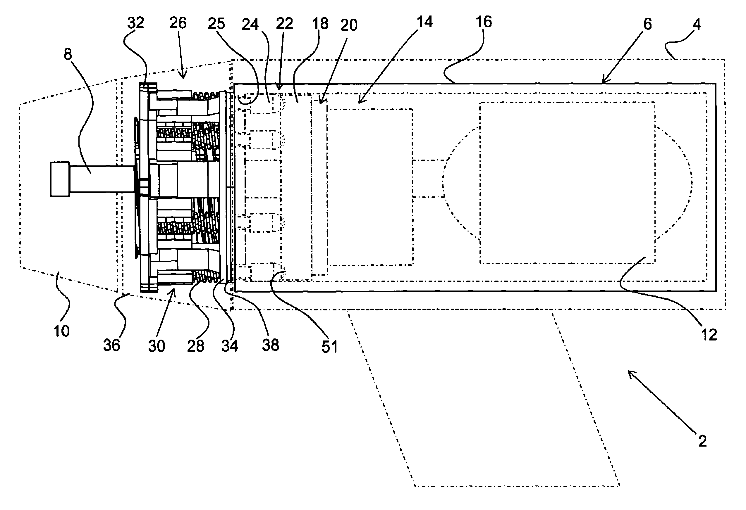
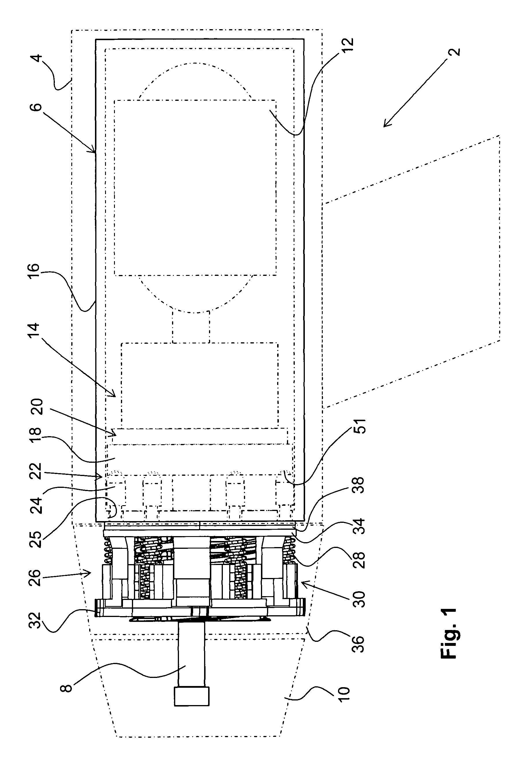
[0020]An electrically driven power tool 2 according to the invention, which is shown in FIG. 1, is formed, e.g., as a screw-driving tool. The power tool 2 has a housing 4 in which a tool drive, which is generally designated with reference numeral 6 is located. The drive 6 applies a torque to a spindle-shaped driven member 8. On the driven member 8, there is supported a working tool receptacle 10 such as, e.g., a drill chuck which is rotated by the drive 6 about an axis A. The drive 6 includes a motor 12 and a transmission mechanism 14 both located in a drive housing 16 fixedly secured in the tool housing 4.

[0021]The drive 6 further has a control element 18, e.g., in form of a planetary gear ring that cooperates with a schematically shown gear means 20, e.g., in form of a stage of planetary gears.

[0022]Between the control element 18 and the drive housing 16, there is provided a slip clutch that is generally designated with a reference numeral 22. The clutch 22 has a plurality of clut...


PUM

PropertyMeasurementUnit
torqueaaaaaaaaaa
relative displacementaaaaaaaaaa
resistance torqueaaaaaaaaaa

Abstract

A power tool includes an output member (8) projecting from the tool housing (4), a drive (6) located in the housing for rotating the output member (8), and a slip clutch (22) for transmitting torque from the drive (6) to the output member (8) and including a plurality of clutch elements (24) retained against rotation relative to the housing (4), a plurality of separate spring elements (28) for adjustable preloading the clutch elements (24) against the counter-clutch elements (51) of the control element (18) for retaining the control element (18) against rotation upon application of the torque thereto until threshold of the torque is reached, and a common support element for supporting the spring elements and movable relative to the housing (4).

Description

BACKGROUND OF THE INVENTION[0001]1. Field of the Invention[0002]The present invention relates to a power tool including a housing, an output member projecting from the housing, a drive located in the housing for rotating the output member about an axis, and a slip clutch for transmitting torque from the drive to the output member. The slip clutch has a plurality of clutch elements retained against rotation relative to the housing, a control element having a respective plurality of counter-clutch elements cooperating with the plurality of clutch elements, and a plurality of separate spring elements for preloading the clutch elements against the counter-clutch elements of the control element. Thereby, the control element is retained against rotation upon application of the torque thereto until threshold of the torque is reached. A rotatable adjustment element adjusts the preload applied by the spring elements.[0003]2. Description of the Prior Art[0004]In the power tools of the type de...

Claims


Application Information

Patent Timeline
Patent Type & Authority Patents(United States)
IPC IPC(8): B23C9/00
CPCB25B23/141B25F5/001F16D43/206
Inventor SPIELMANN, DAVIDGERSCHWILER, OTHMARBREITENMOSER, ARMINBREITENMOSER, LEGAL REPRESENTATIVE, REMO
Owner HILTI AG
Learn More