Vacuum filtration device

a vacuum filtration and vacuum technology, applied in the direction of liquid degasification, membranes, separation processes, etc., can solve the problems of reducing the filtration rate adversely, reducing the filtration rate, and difficult to achieve the reestablishing liquid flow

Inactive Publication Date: 2010-10-05
MILLIPORE CORP
View PDF21 Cites 8 Cited by
  • Summary
  • Abstract
  • Description
  • Claims
  • Application Information

AI Technical Summary

Benefits of technology

[0016]The present invention is a filter assembly for vacuum filtration formed of a closed housing having an upper portion and lower portion, a filter separating the upper portion from the lower portion of the housing, an inlet formed in the upper housing, an outlet and a vacuum port formed in the lower portion, a gasket arranged at a lowermost surface of the lower portion and the upper portion of the housing has a cross sectional design of a height and volume sufficient to retain any air that may be introduced from the feed liquid and from within the filter assembly itself into the filter assembly, under normal operating conditions, without disrupting the vacuum flow. Preferably, the upper portion cross-sectional design is of a curved shape, preferably in the form of a dome, having a height and volume sufficient to trap any air that might enter from the system itself, including tubing and keep it away from the membrane surface. Optionally, the upper portion of the housing may also contain a vent, particularly a vent controlled by a mechanical, manual, or automatic valve, for the removal of air periodically from the upper portion, especially when a large incursion of air has occurred.
[0017]This invention allows one to maximize the effective filtration area of the device by eliminating the need for a hydrophobic membrane or portion in the active filtration area. It also prevents air from interfering with the vacuum filtration by trapping it away from the membrane surface and optionally, occasionally venting it. Moreover, it eliminates the problem of integrity testing which exists with the dual philic / phobic membrane systems.
[0018]It is an object of the present invention to provide a vacuum filter assembly for filtering a feed liquid into a filtrate container comprising a closed housing having an upper portion and a lower portion, an inlet formed in the upper portion of the housing, an outlet formed in the lower portion of the housing filter sealed in a liquid tight manner in the housing upstream of the outlet, a vacuum port in the lower portion of the housing downstream of the filter and located to communicate with an interior of the filtrate container to produce a vacuum within the filtrate container when the housing is attached to the filtrate containers and when the vacuum port is connected to a vacuum supply, the housing containing a gasket at its lower most surface for establishing a seal for the vacuum with the filtrate container, the filter being a microporous hydrophilic filter and the upper portion of the housing having a cross sectional design wherein the design is of a height and volume sufficient to retain any air that may be introduced from the feed liquid and from within the filter assembly itself into the filter assembly under normal operating conditions without disrupting the vacuum flow.

Problems solved by technology

Reestablishing the liquid flow can be difficult to achieve.
Likewise, the use of a hybrid membrane (part hydrophilic, part hydrophobic) is expensive and requires a determination of the proper balance of the respective philic / phobic areas.
Too much phobic area reduces the filtration rate adversely.
Likewise, too little phobic area makes restarting as difficult as if no phobic region existed.
Additionally, the phobic membrane or area is in contact with the fluid being filtered and will over time wet out or become clogged or fouled with contaminants or product such as proteins.
This results in an irreversible air locking upon an air incursion as the phobic area no longer functions.
Both versions are difficult to integrity test with standard bubble point procedures due to the presence of the philic / phobic membranes at the same time.
Another problem with current closed filtration devices is that these devices are sensitive to small intrusions of air because the upper housing chamber is too small to hold any air away from the membrane, and therefore relies on the hybrid membrane to provide the sole means for evacuating trapped air.

Method used


Image

  • Vacuum filtration device
  • Vacuum filtration device
  • Vacuum filtration device

Examples


Embodiment Construction

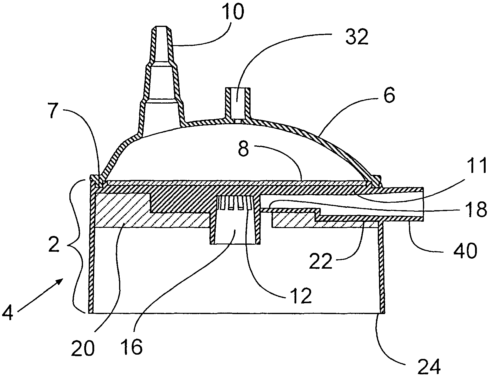
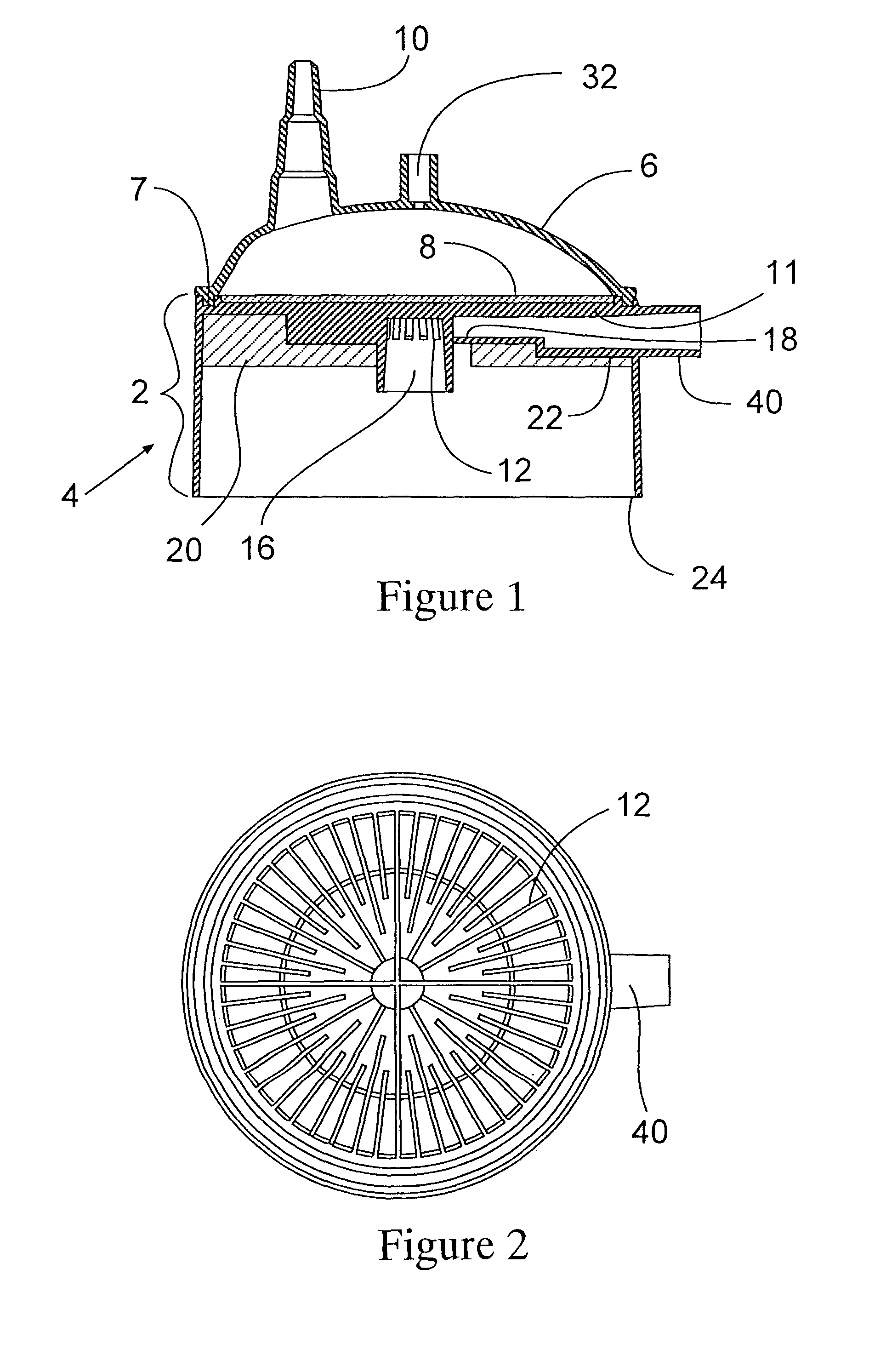
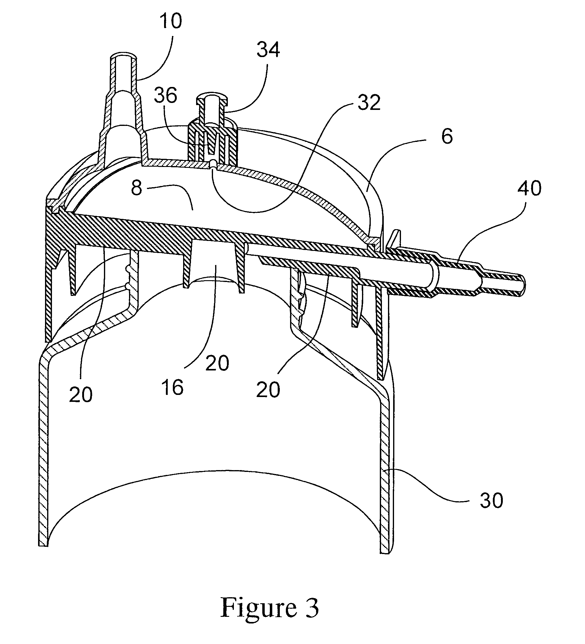
[0033]The present invention is a device comprised of several major elements; a closed housing 2 formed of a lower portion 4 and an upper portion 6, a filter 8 which separates the upper portion 6 from the lower portion 4 in a liquid tight manner such that all fluid entering the lower portion 4 does so by passing through the filter 8 from the upper portion 6. The upper portion 6 is bonded to the lower portion 4 around their joining peripheries 7 so as to form an air tight, closed system for vacuum filtration. The portions can be joined by thermal bonding, ultrasonic welding, solvent bonding, adhesives, mechanical fits such as press-fits and snap-fits, and the like.

[0034]The upper portion 6 has an inlet 10 and the upper portion 6 has a cross sectional design of a height, shape and volume such that small volumes of air that may enter the upper portion 6 are retained within the upper regions of the upper portion 6 away from the membrane 8 so that vacuum filtration may continue uninterrup...


PUM

PropertyMeasurementUnit
pore sizeaaaaaaaaaa
pore sizeaaaaaaaaaa
pore sizesaaaaaaaaaa

Abstract

The present invention is a filter assembly for vacuum filtration formed of a housing having an upper portion and lower portion, a filter separating the upper from the lower portion of the housing, an inlet formed in the upper housing, an outlet and a vacuum port formed in the lower portion, a gasket arranged at a lowermost surface of the lower portion and the upper portion is having a height sufficient to trap any air that might enter and keep it away from the membrane surface. Preferably, it is of a curved shape, preferably in the form of a dome. Optionally, the upper portion of the housing may also contain a vent, particularly a vent controlled by a valve, for the removal of air periodically from the upper portion, especially when a large incursion of air has occurred.

Description

RELATED APPLICATIONS[0001]This application claims the benefit of U.S. Provisional Application No. 60 / 446,897, filed Feb. 12, 2003, and U.S. Provisional Application No. 60 / 523,264, filed Nov. 19, 2003, and U.S. Provisional Application No. 60 / 531,410, filed Dec. 19, 2003.[0002]The present invention relates to a device for vacuum driven filtration. More particularly, it relates to a closed device for vacuum driven sterile filtration.BACKGROUND OF THE INVENTION[0003]Several device designs have been made for filtering a feed liquid into a filtrate container. These are typically used to clarify and sterilize biological solutions, such as fetal calf serum, tissue culture media and the like. They may be an open device, meaning that their supply is open to the atmosphere or they may be a closed type of device in which the system is closed to the atmosphere. In an open device, the user must transfer the feed liquid from a storage vessel to the filter device, thus adding an added manual step t...

Claims


Application Information

Patent Timeline
Patent Type & Authority Patents(United States)
IPC IPC(8): B01D29/92B01D35/00B01D35/01B01D35/02B01D61/16B01D61/18B01D61/20B01D63/08
CPCB01D61/16B01D61/18B01D61/20B01D63/08B01D61/145B01D61/147B01D2311/04B01D2311/14
Inventor SCOTT, CHRIS A.DUNLEAVY, MATTHEW JOHNBONHOMME, LOUIS
Owner MILLIPORE CORP
Why Eureka
Try Eureka