
Thermoelectric and pyroelectric energy conversion devices

a technology of energy conversion device and thermoelectric power, which is applied in the direction of device material selection, optical radiation measurement, instruments, etc., can solve the problems of low conversion efficiency, low conversion efficiency, and typical combustion engine development of only 25% useful shaft rotation power, so as to improve the efficiency of thermoelectric generation device and improve the effect of thermoelectric conversion efficiency

Inactive Publication Date: 2010-10-05
TRANSLUCENT PHOTONICS +1
View PDF26 Cites 49 Cited by
  • Summary
  • Abstract
  • Description
  • Claims
  • Application Information

AI Technical Summary

Benefits of technology

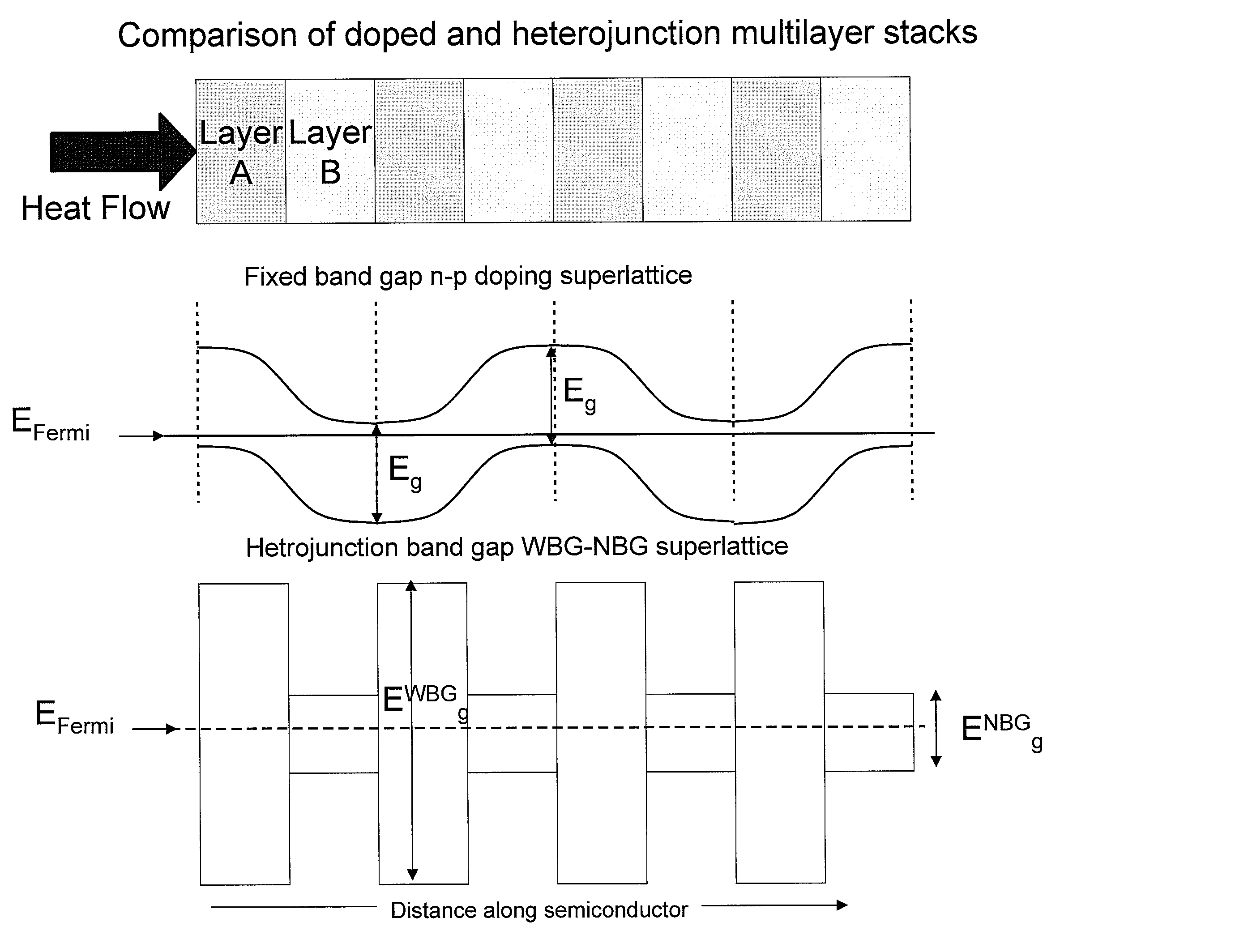
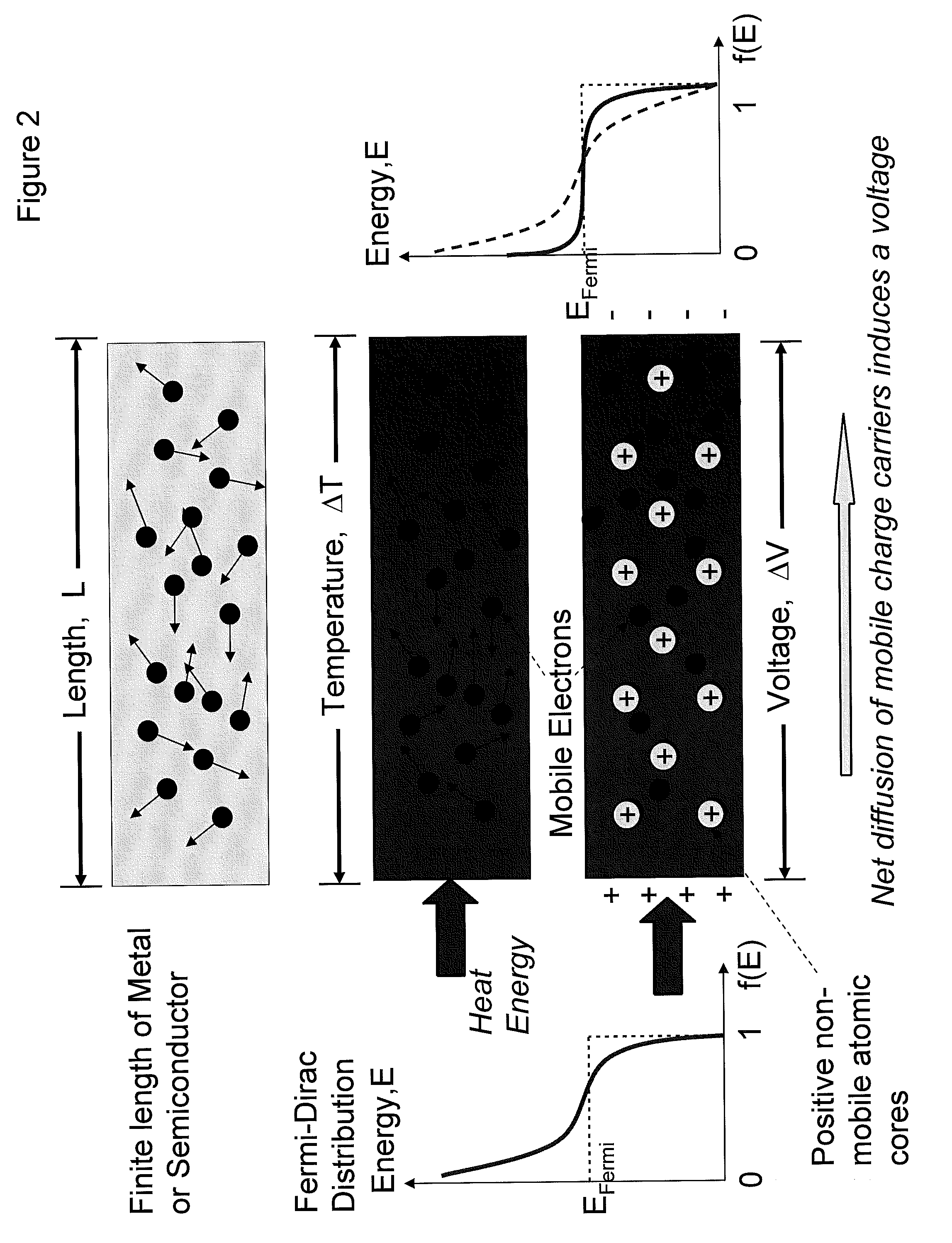
[0014]An aspect of the present invention is to improve the efficiency of thermoelectric generation devices beyond those of prior art devices by using new thermoelectric materials and device configurations. The improvement of thermoelectric conversion efficiency enables new applications for large scale electricity generation from thermal sources, be it from waste heat recovery, direct conversion of heat energy from the combustion of fossil fuel and / or nuclear fission and / or nuclear fusion and / or thermal energy from solar and / or geothermal sources.
[0017]The present invention solves prior art thermoelectric deficiencies by introducing high temperature thermoelectric materials and scaleable device architectures. In one embodiment, materials composed of germanium-rare-earth-metal compounds and / or silicon-rare-earth-metal compounds are used to form band gap engineered electronic junctions capable of efficient thermoelectric conversion of thermal radiation into electrical energy.
[0020]The present invention seeks to alleviate this heat problem in ULSICs and more particularly in portable ULSIC systems requiring prolonged battery life, by recovering wasted heat energy form dissipative processes in ULSICs via active and passive transistor leakage currents and converting the said microscopic and macroscopic heat energy dissipated back into useful electrical energy to power the same ULSICs. Such a regenerative process of heat conversion back into electrical power suitable for driving ULSICs would significantly aid in the prolong of battery lifetime of portable communications and computing devices and systems.

Problems solved by technology

A disadvantage of prior art techniques is the low conversion efficiency.
If a load is connected to the sample, the electric power is consumed at the load.
In general, a typical combustion engine develops only 25% useful shaft rotation power with as much as 40% waste heat energy via exhaust gas.
Therefore, there would be considerable cost, environmental and safety gains for direct energy conversion of waste heat from a thermal source into electricity.

Method used


Image

  • Thermoelectric and pyroelectric energy conversion devices
  • Thermoelectric and pyroelectric energy conversion devices
  • Thermoelectric and pyroelectric energy conversion devices

Examples


Embodiment Construction

[0120]Thermoelectric materials so far used for practical applications include Bi2Te3, PbTe, and Si1-xGex. Large scale application of these materials has not occurred due to one or more problems relating to poor ZT, low melting or decomposition temperature, harmful and / or scarce elements and / or cost. Bismuth telluride Bi2Te3 has the unique properties of complex hexagonal crystal structure, small bandgap energy Eg=0.15 eV, relatively high electron and hole mobilities (μe=800 cm2 / Vs &μh=400 cm2 / Vs) and low thermal conductivity (κth˜1-2 W / mK). N-type BiSb is superior at low temperatures, but does not have a p-type counterpart. Bi2Te3 exhibits the highest performance near room temperature, and is used for cooling applications such as commercially available Peltier coolers. PbTe shows the highest performance near 500-600° K., and Si1-xGex is superior above 1000° K. The compound semiconductors BiSb, PbTe and Si1-xGex all have a zinc-blende type crystal structure. It is noteworthy that sing...


PUM

PropertyMeasurementUnit
channel lengthaaaaaaaaaa
carrier densityaaaaaaaaaa
melting pointaaaaaaaaaa

Abstract

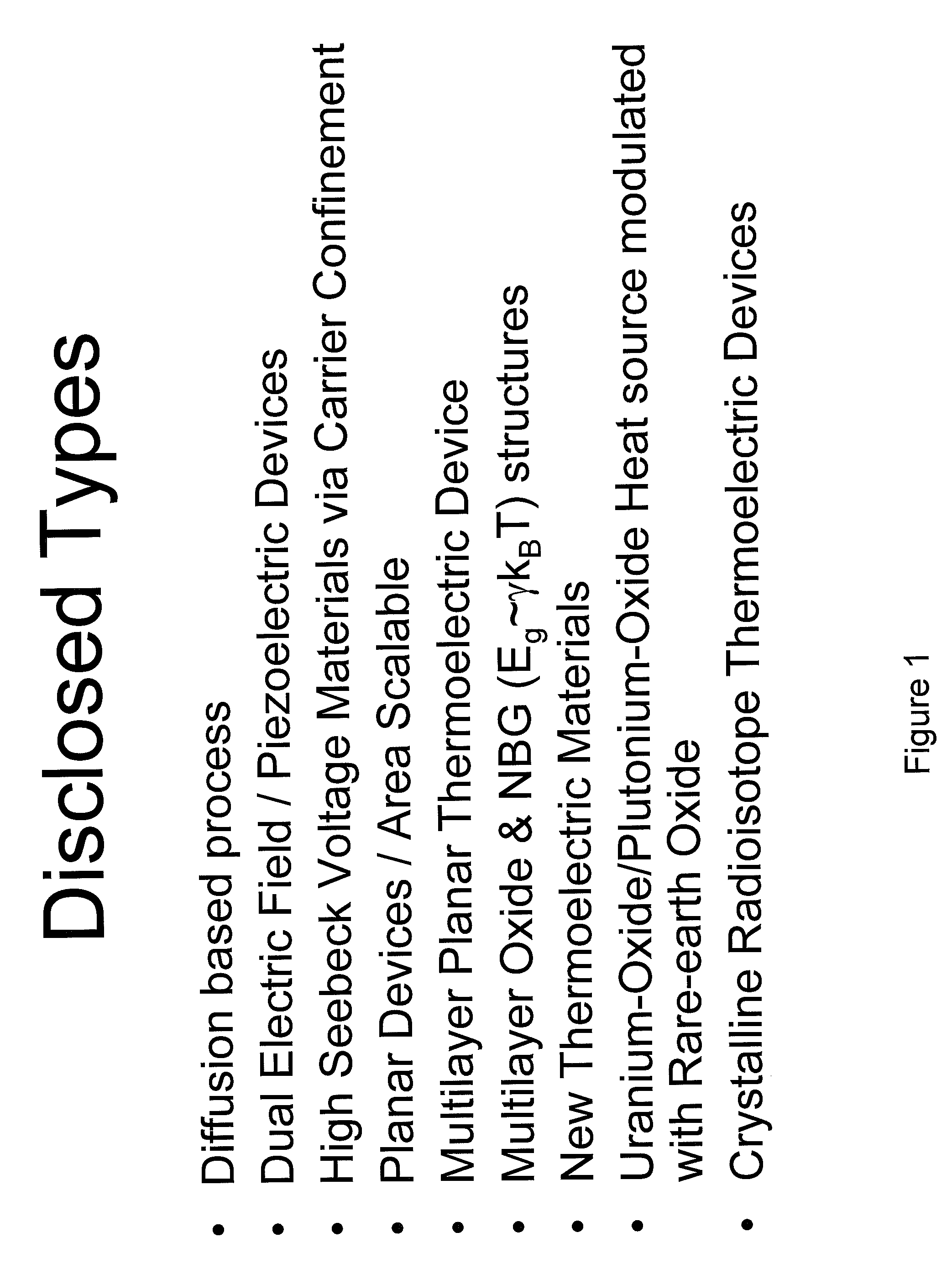
New thermoelectric materials and devices are disclosed for application to high efficiency thermoelectric power generation. New functional materials based on oxides, rare-earth-oxides, rare-earth-nitrides, rare-earth phosphides, copper-rare-earth oxides, silicon-rare-earth-oxides, germanium-rare-earth-oxides and bismuth rare-earth-oxides are disclosed. Addition of nitrogen and phosphorus are disclosed to optimize the oxide material properties for thermoelectric conversion efficiency. New devices based on bulk and multilayer thermoelectric materials are described. New devices based on bulk and multilayer thermoelectric materials using combinations of at least one of thermoelectric and pyroelectric and ferroelectric materials are described. Thermoelectric devices based on vertical pillar and planar architectures are disclosed. The advantage of the planar thermoelectric effect allows utility for large area applications and is scalable for large scale power generation plants.

Description

[0001]Applicant claims priority from U.S. Provisional application 60 / 820,438, filed on Jul. 26, 2006,STATEMENT REGARDING FEDERALLY SPONSORED RESEARCH OR DEVELOPMENT[0002]This work was supported by a technology investment grant by DARPA / MTO Electronic and Photonic Integrated Circuit (EPIC) program contract No. W911NF-05-3-0001.CROSS-REFERENCE TO RELATED APPLICATIONS.[0003]Applications and patent Ser. Nos. 09 / 924,392, 10 / 666,897, 10 / 746,957, 10 / 799,549, 10 / 825,912, 10 / 825,974, 11 / 022,078, 11 / 025,363, 11 / 025,680, 11 / 025,681, 11 / 025,692, 11 / 025,693, 11 / 084,486, 11 / 121,737, 11 / 187,213, U.S. 20050166834, U.S. 20050161773, U.S. 20050163692, Ser. Nos. 11 / 053,775, 11 / 053,785, 11 / 054,573, 11 / 054,579, 11 / 054,627, 11 / 068,222, 11 / 188,081, 11 / 253,525, 11 / 254,031, 11 / 257,517, 11 / 257,597, 11 / 393,629, 11 / 398,910, 11 / 472,087, 11 / 788,153, 60 / 533,378, 60 / 820,438, 60 / 811,311, 60 / 944,369 U.S. Pat. Nos. 7,018,484, 6,734,453, 7,023,011, 6,858,864, 7,037,806, 7,135,699, and 7,199,015, all held by the same a...

Claims


Application Information

Patent Timeline
Patent Type & Authority Patents(United States)
IPC IPC(8): H01L35/12H01L35/22H01L35/30H01L35/14H01L35/16H01L35/20H01L37/00H01L41/00H02N2/00G01J5/00
CPCH01L35/22H01L35/26H01L35/32H01L37/025H01L41/18H10N10/857H10N10/855H10N15/15H10N10/17H10N30/85
Inventor ATANACKOVIC, PETAR B.
Owner TRANSLUCENT PHOTONICS
Learn More