Combined type transformer and buck-boost circuit using the same

a technology of buck-boost circuit and transformer, which is applied in the direction of electric variable regulation, process and machine control, instruments, etc., can solve the problems of reducing the voltage boost ratio, unsatisfactory magnetic saturation of the magnetic core, and difficult to reduce the size and weight of the dc/dc converter

Inactive Publication Date: 2010-10-05
HONDA MOTOR CO LTD +1
View PDF24 Cites 23 Cited by
  • Summary
  • Abstract
  • Description
  • Claims
  • Application Information

AI Technical Summary

Benefits of technology

[0013]In view of the foregoing prior art problems, it is an object of the present invention to provide a small-size, lightweight combined type transformer having functions of both an inductor and transformer, and a buck-boost circuit employing such a small-size, lightweight combined type transformer.
[0024]In the combined type transformer of the present invention, the transformer and inductor, which used to be constructed as separate electric components in the prior art, are integrally formed with the winding portions projecting outwardly from the transformer core (i.e., projecting coil portions) used as coils of the inductor. By virtue of such shared use of the coils between the transformer and the inductor, the inventive combined type transformer can be constructed in a compact size and installed in a narrow space, making efficient use of the limited space with spatial waste minimized. As a result, it is possible to not only reduce the total length of the windings located in the transformer and inductor, but also achieve a lower I2R loss.
[0025]Namely, according to the present invention, the transformer and inductor are constructed integrally as a single structure of a compact size, using only structurally-essential portions and making efficient use of a limited space, so that the combined type transformer can be implemented in significantly reduced size and weight and with minimized wasteful space.

Problems solved by technology

Further, if an attempt is made to increase a voltage boost ratio in the voltage boosting circuit 100, undesired magnetic saturation of the magnetic core and lowering of the voltage boost ratio may occur.
In the case where the inductor and transformer, constituting the DC / DC converter, are provided as separate components as set forth above, it would be difficult to reduce the size and weight of the DC / DC converter.
As a consequence, the (mutual) inductance would undesirably stay at low values as compared to the cubic volumes of the coils, which also makes it difficult to reduce the size and weight of the DC / DC converter.
Also, the large connecting portions between the inductor and the transformer would undesirably lower the power conversion efficiency due to a large conduction loss.

Method used


Image

  • Combined type transformer and buck-boost circuit using the same
  • Combined type transformer and buck-boost circuit using the same
  • Combined type transformer and buck-boost circuit using the same

Examples


Embodiment Construction

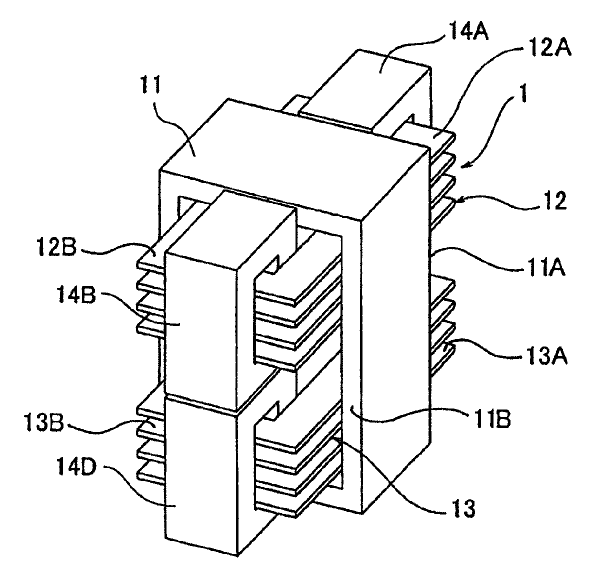
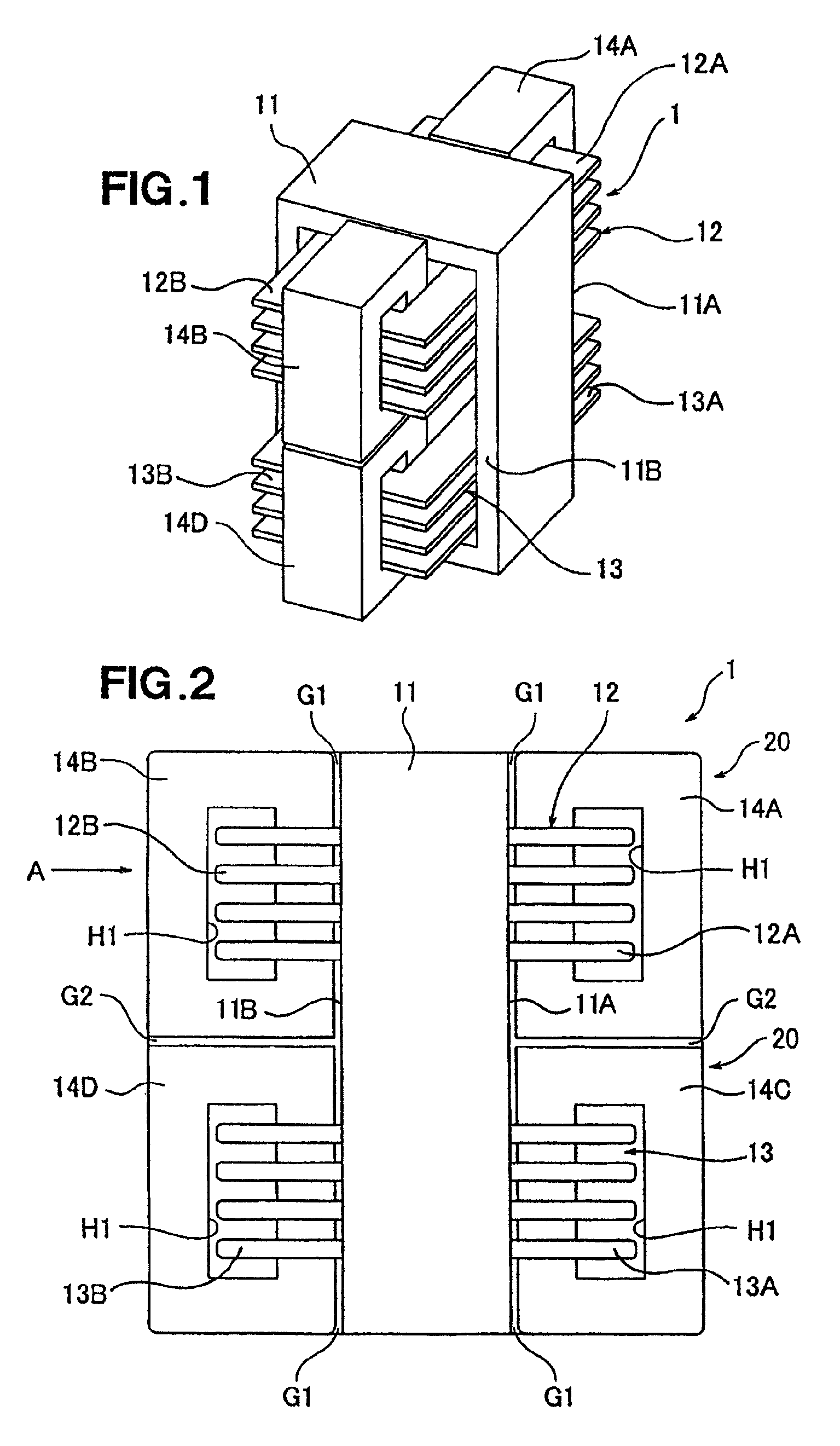
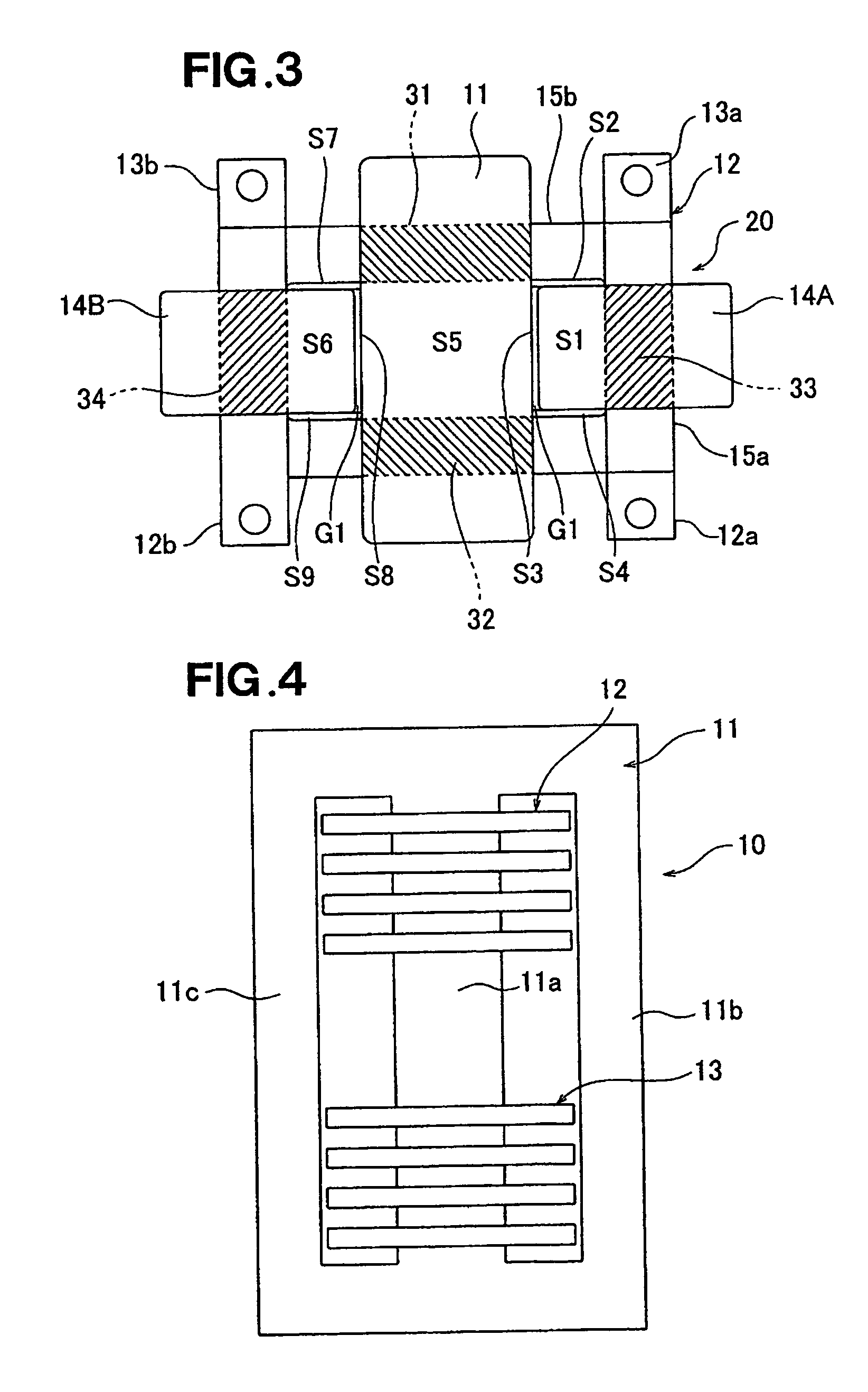
[0057]First, with reference to FIGS. 1-4, a description will be made as to the shape and construction of a combined type transformer 1 according to a preferred embodiment of the present invention. FIGS. 1, 2 and 3 respectively show in perspective, front elevation and top plan the combined type transformer 1, while FIG. 4 shows the combined type transformer 1 as viewed in a direction of arrow A of FIG. 2 (with inductor cores removed).

[0058]The combined type transformer 1 includes a transformer core 11 made of, for example, ferrite, and, as shown in FIG. 4, the transformer core 11 has a middle magnetic path portion 11a, and side magnetic path portions 11b and 11c located at opposite sides of the middle magnetic path portion 11a in parallel to the latter. The transformer core 11 functions as an iron core that allows the transformer 10 to perform a voltage transforming action. Coils 12 and 13 are wound around upper and lower regions, respectively, of the middle magnetic path portion 11a...


PUM

PropertyMeasurementUnit
widthaaaaaaaaaa
heat resistanceaaaaaaaaaa
electric currentaaaaaaaaaa

Abstract

Combined type transformer includes: a transformer core; first and second coils provided with respect to the transformer core; first and second inductor cores provided around the first coil; and third and fourth inductor cores provided around the second coil. The transformer core and the first and second coils constitute a transformer, the first coil and the first and second inductor cores constitute a first inductor, and the second coil and the third and fourth inductor cores constitute a second inductor.

Description

FIELD OF THE INVENTION[0001]The present invention relates generally to combined type transformers and buck-boost circuits using such a combined type transformer, and more particularly to an improved combined type transformer having both of inductor and transformer functions and an improved buck-boost circuit using the improved combined type transformer.BACKGROUND OF THE INVENTION[0002]Heretofore, there have been proposed various voltage boosting circuits (for example, JP 2003-111390 A and JP 2003-216255 A). FIG. 22 hereof shows a fundamental circuit structure of the conventional voltage boosting circuit 100 disclosed in one of the above-identified publications.[0003]As shown in FIG. 22, the voltage boosting circuit 100 includes an input-side smoothing capacitor 102, a coil (inductor) 101, a switching element 103, a diode 104, and an output-side smoothing capacitor 105. The input-side smoothing capacitor 102 is connected between a negative-pole terminal 106 and an input terminal 107 ...

Claims


Application Information

Patent Timeline
Patent Type & Authority Patents(United States)
IPC IPC(8): H01F27/28H01F17/04H01F27/24H01F21/06G05F1/00
CPCH01F27/385H01F37/00H02M3/1584
Inventor NAGANO, MASAOHIRAKAWA, MITSUAKISHIMIZU, TOSHIHISA
Owner HONDA MOTOR CO LTD
Why Eureka
Try Eureka