Method for determining non-broadcast multiple access (NBMA) connectivity for routers having multiple local NBMA interfaces

a router and multiple access technology, applied in the field of routers with multiple local nbma interfaces, can solve the problems of potential bottlenecks, unreasonably large routing overhead, and complicated incentives to operate ip over atm backbones, and achieve the effects of avoiding overhead, introducing latency, and facilitating migration

Inactive Publication Date: 2010-10-05
AT&T INTPROP I L P
View PDF8 Cites 99 Cited by
  • Summary
  • Abstract
  • Description
  • Claims
  • Application Information

AI Technical Summary

Benefits of technology

[0009]It is another object of the present invention to retain architectural independence between the layer 2 switched network and layer 3 connectionless networks in order to allow for independent design and evolution of the networks.
[0010]It is another object of the present invention to avoid the overhead typically associated with address resolution, which can introduce latency and exacerbate the problems of out-of-order delivery of packets in the network.
[0011]It is another object of the present invention to provide an architecture that ensures connectivity among the routers and allows for the possibility of shortcut setup failure given that virtual circuit connection resources are limited.
[0012]It is another object of the present invention to keep the protocol, storage, and computational overhead to a minimum and to build on existing tested routing protocols allowing the present invention to work with existing router hardware.
[0013]It is another object of the present invention to provide for incremental deployment and ease of migration.
[0014]The present invention achieves these objectives by providing a robust and efficient architecture for routing in a very large autonomous system where many of the layer 3 routers are attached to a common connection-oriented layer 2 subnetwork, such as an ATM network. In a preferred embodiment of the invention, a permanent topology of routers coupled to the subnetwork is connected by permanent virtual circuits. The mesh of virtual circuits can be as sparse as a spanning tree, but will normally consist of a denser set of connections for reliability. The routers use extensions to OSPF (Open Shortest Path First) mechanisms to calculate optimal paths in the permanent topology. The routers can further take advantage of both intra-area and inter-area shortcuts through the layer 2 network to improve network performance. The routers pre-calculate shortcuts using information from link state packets broadcast by other routers and store the shortcuts to a given destination in a forwarding table, along with corresponding entries for a next hop along the permanent topology. The present invention allows the network to continue to operate correctly if layer 2 resource limitations preclude the setup of additional shortcuts, if for example the necessary connection capacity is temporarily in use. Packets can still make use of the virtual circuits in the permanent topology if a shortcut cannot be setup.

Problems solved by technology

The incentive to operate IP over an ATM backbone, however, has been complicated by various internetworking issues arising between IP and ATM.
The simple approach of having all of the routers connected to the ATM cloud peer with each other resulting in N2 adjacencies, does not scale as the size of the routing tables and the routing overhead grow unreasonably large for network sizes of interest.
These servers represent a potential bottleneck, as well as raise issues with regard to scaling and reliability.
A concern with these approaches is that they fail to maintain architectural independence between the layer 2 and layer 3 networks.
This coupling between layers is undesirable, particularly in a large provider network where the layer 2 network may be designed for multiple services and is not necessarily optimized to meet the needs of the IP layer.
The above approaches also limit deployment flexibility in that, for example, the scope of the layer 2 and layer 3 networks may necessitate hierarchical approaches to routing.
Hybrid switches require support for both ATM and MPLS protocols on every switch, which introduces both architectural and management complexity.

Method used


Image

  • Method for determining non-broadcast multiple access (NBMA) connectivity for routers having multiple local NBMA interfaces
  • Method for determining non-broadcast multiple access (NBMA) connectivity for routers having multiple local NBMA interfaces
  • Method for determining non-broadcast multiple access (NBMA) connectivity for routers having multiple local NBMA interfaces

Examples


Embodiment Construction

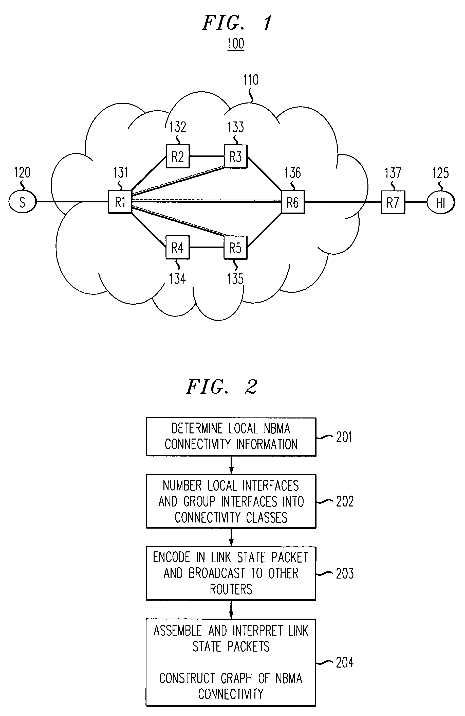
[0030]With reference to FIG. 1, a diagram of a communication network 100 is shown illustrating an embodiment of the present invention. The network 100 has multiple routers 131-137, some of which are coupled to a connection-oriented non-broadcast multiple access (NBMA) network 110. For illustration purposes only, network 110 is assumed to be an ATM network, although those of skill in the art will easily recognize that the present invention has application to other connection-oriented networks. It is assumed that it is more efficient to traverse many hops of the routed 150 network by a single NBMA virtual circuit (shortcut). It is also assumed that the virtual circuits are in sufficiently short supply as to preclude interconnecting the routers in a single mesh topology, and that the overhead of setting up and tearing down virtual circuits is too costly for the connection-oriented network to directly emulate a connectionless network.

[0031]In FIG. 1, a source 120 is connected to a route...


PUM


Abstract

The present invention discloses an efficient architecture for routing in a very large autonomous system where many of the layer 3 routers are attached to a common connection-oriented layer 2 subnetwork, such as an ATM network. In a preferred embodiment of the invention, a permanent topology of routers coupled to the subnetwork is connected by permanent virtual circuits. The routers can further take advantage of both intra-area and inter-area shortcuts through the layer 2 network to improve network performance. The routers pre-calculate shortcuts using information from link state packets broadcast by other routers and store the shortcuts to a given destination in a forwarding table, along with corresponding entries for a next hop along the permanent topology. The present invention allows the network to continue to operate correctly if layer 2 resource limitations preclude the setup of additional shortcuts.

Description

CROSS REFERENCE TO RELATED APPLICATIONS[0001]This application is a continuation of prior application Ser. No. 09 / 345,121 filed Jul. 6, 1999 now U.S. Pat. No. 6,711,152, which claims priority to Provisional Application Ser. No. 60 / 091,846 filed on Jul. 6, 1998, both of which are incorporated herein by reference.FIELD OF THE INVENTION[0002]This invention relates generally to a method and apparatus for establishing communication over a telecommunications network and, more particularly, to a network comprising fast switches operating at the datalink layer and interconnecting network layer routers.BACKGROUND OF THE INVENTION[0003]As communication networks grow in both size and scale, the speed at which packets need to be forwarded becomes higher and higher. The traditional approach to achieve higher switching speeds has been to build fast switches that operate at the datalink layer (otherwise known in the art as layer 2 of the seven-layer OSI model). A more recent trend, spurred on by th...

Claims


Application Information

Patent Timeline
Patent Type & Authority Patents(United States)
IPC IPC(8): H04L12/28H04L12/56
CPCH04L45/04
Inventor KALMANEK, JR., CHARLES ROBERTLAUCK, ANTHONY GRAMAKRISHNAN, KADANGODE K.
Owner AT&T INTPROP I L P
Why Eureka
Try Eureka