Method and device for suppressing electromagnetic background radiation in an image

a technology of electromagnetic background radiation and electromagnetic filter, which is applied in the field of suppressing electromagnetic background radiation in images, can solve the problems that the filter cannot be completely eliminated, the background radiation from foreign sources is attenuated, etc., and achieves the effects of high positional resolution, reliable, and economical position determination of laser spots

Active Publication Date: 2010-10-05
LEICA GEOSYSTEMS AG
View PDF29 Cites 5 Cited by
  • Summary
  • Abstract
  • Description
  • Claims
  • Application Information

AI Technical Summary

Benefits of technology

[0036]The interference suppression is also possible by means of sensor arrays in the lower price segment. Comparatively low measuring frequencies present in the case of these sensors are not a problem in the evaluation using this method. Thus, a reliable, economical position determination for laser spots is permitted with high positional resolution.
[0037]The method has advantages particularly when sensor arrays are used for increasing the positional resolution of a laser spot search.

Problems solved by technology

Background radiation from foreign sources is attenuated by the filter but as a rule cannot be entirely eliminated.

Method used


Image

  • Method and device for suppressing electromagnetic background radiation in an image
  • Method and device for suppressing electromagnetic background radiation in an image
  • Method and device for suppressing electromagnetic background radiation in an image

Examples


Embodiment Construction

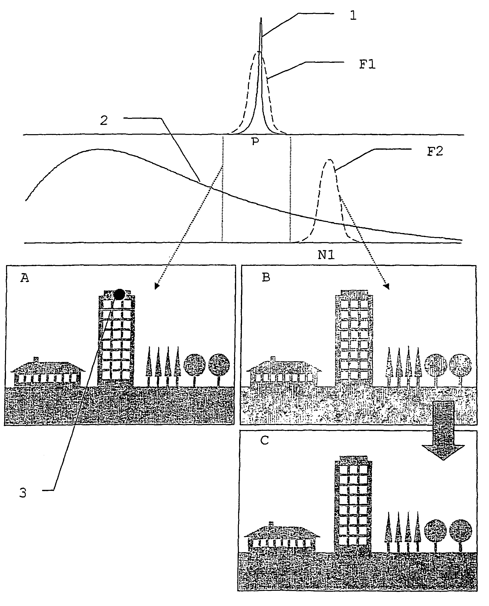
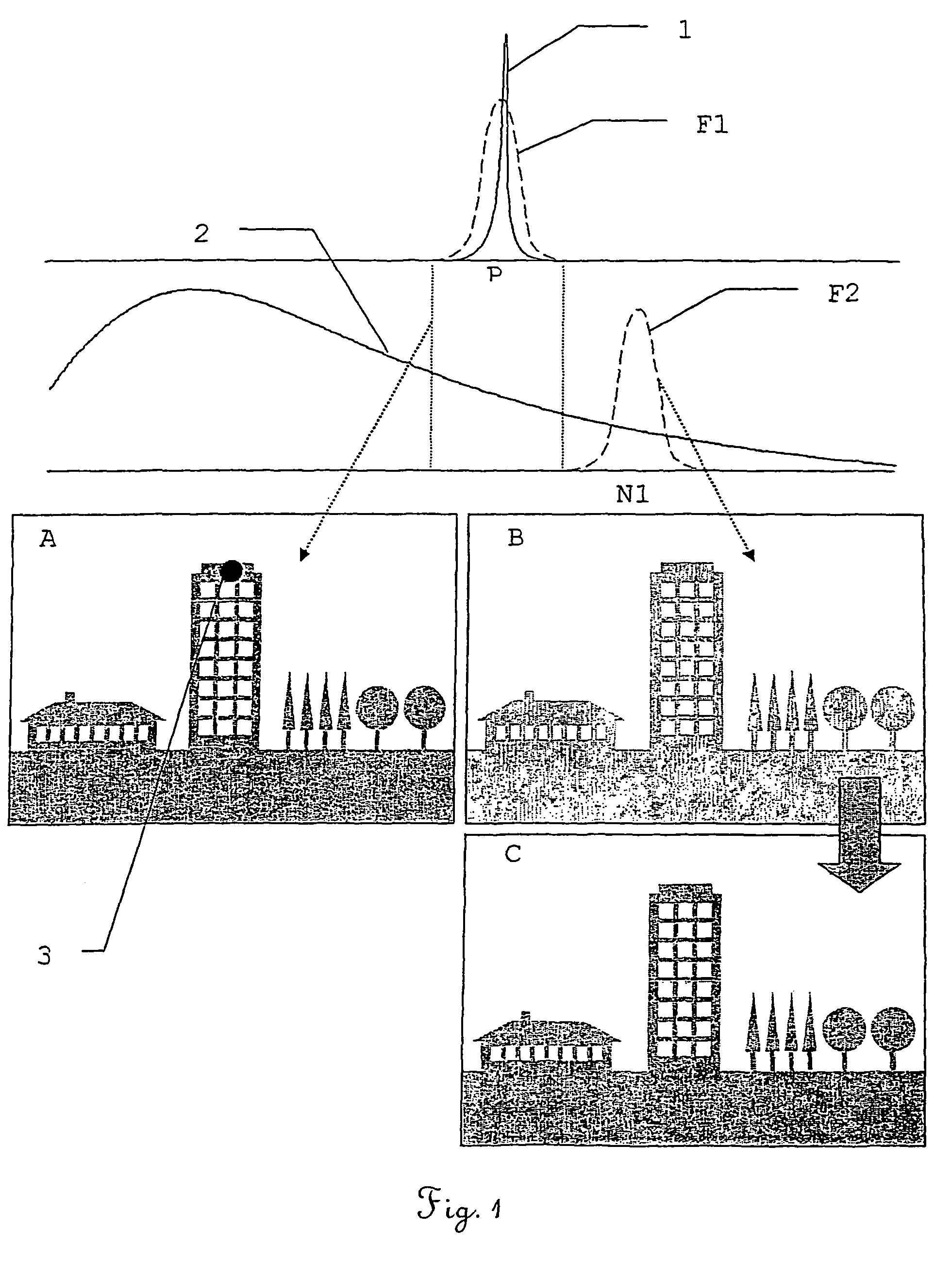
[0045]FIG. 1 schematically shows the derivation of a background C for a P-image A which contains a laser spot 3 which is used, for example, for marking a point to be measured on a building. This diagram describes, purely schematically and in general formulation, the fundamental concept of the method according to the invention, without being concerned with special application-related specifics, in particular with regard to the number and design of filters. These are shown by way of example for some examples in the other figures.

[0046]In the upper part of the figure, the separate, spectral curves of the laser radiation 1 are shown as a signal to be extracted and a background radiation 2. The laser radiation 1 has a line character while the background radiation or interfering radiation has, by way of example, the continuous spectral curve of a thermal emitter or of an approximately thermal emitter, such as, for example, sunlight. However, the background radiation can also originate, fo...


PUM


Abstract

A method for suppressing electromagnetic background radiation in the image according to a precharacterization, a device for carrying out the method according to a precharacterization, a measuring instrument, and a use of the device for identifying a laser signal as a mark for subsequent measuring processes as well as for identifying a source of a laser signal.

Description

BACKGROUND[0001]The invention relates to a method for suppressing electromagnetic background radiation in an image according to a precharacterization, a device for carrying out the method according to a precharacterization, a measuring instrument, and a use of the device for identifying a laser signal as a mark for subsequent measuring processes as well as for identifying a source of a laser signal.[0002]The detection of individual signals or complete signatures of electromagnetic radiation has a wide range of uses. It is possible to make a distinction between two fundamental objects.[0003]On the one hand, a radiation source (target source) or the real or virtual image thereof is to be detected and its position or its direction determined. Applications exist here, for example, in the automatic orientation of measuring instruments or the detection of radiation sources in the military sector (for example, for detecting an opponent's target illumination or distance measurement, as part...

Claims


Application Information

Patent Timeline
Patent Type & Authority Patents(United States)
IPC IPC(8): G06K9/00G06K9/36G01B11/00F41G3/14G01S7/487G01S17/06G01S17/89
CPCF41G3/145G01S7/487G01S17/89
Inventor KIRSCHNER, HOLGER
Owner LEICA GEOSYSTEMS AG
Why Eureka
Try Eureka