
Gas turbine with heat exchanger for cooling compressed air and preheating a fuel

a technology of heat exchanger and heat exchanger, which is applied in the direction of efficient propulsion technology, mechanical equipment, machines/engines, etc., can solve the problems of entanglement of exergy and unnecessarily large amount of cooling air being used

Inactive Publication Date: 2010-10-12
ALSTOM TECH LTD
View PDF22 Cites 29 Cited by
  • Summary
  • Abstract
  • Description
  • Claims
  • Application Information

AI Technical Summary

Benefits of technology

[0010]A development is distinguished by the fact that the second turbine drives a generator. The shaft output of the second turbine that is obtained can be fed into the power network by means of the generator and therefore increase the overall efficiency of the plant.
[0012]As a further alternative, the shaft output obtained can also be dissipated again elsewhere and consequently the fuel could be heated (in a way similar to a hydraulic dynamometer in test turbines). This happens if, according to another development, the second turbine drives a fuel preheating device in which the fuel is heated by converting kinetic energy into heat. This would preferably be done with liquid fuel, because of the simpler technical solution. Consequently, the “throttling energy” would be advantageously used and fed to the highest energy level in the cyclic process, which would lead to an “optimum” yield with regard to power and efficiency, and would be better than displacing thermal energy into the steam circuit.

Problems solved by technology

Excessive pressure in the turbine cooling system would result in an unnecessarily great amount of cooling air being used.
However, throttling entails loss of exergy, which could otherwise be used in expansion.

Method used


Image

  • Gas turbine with heat exchanger for cooling compressed air and preheating a fuel
  • Gas turbine with heat exchanger for cooling compressed air and preheating a fuel
  • Gas turbine with heat exchanger for cooling compressed air and preheating a fuel

Examples


Embodiment Construction

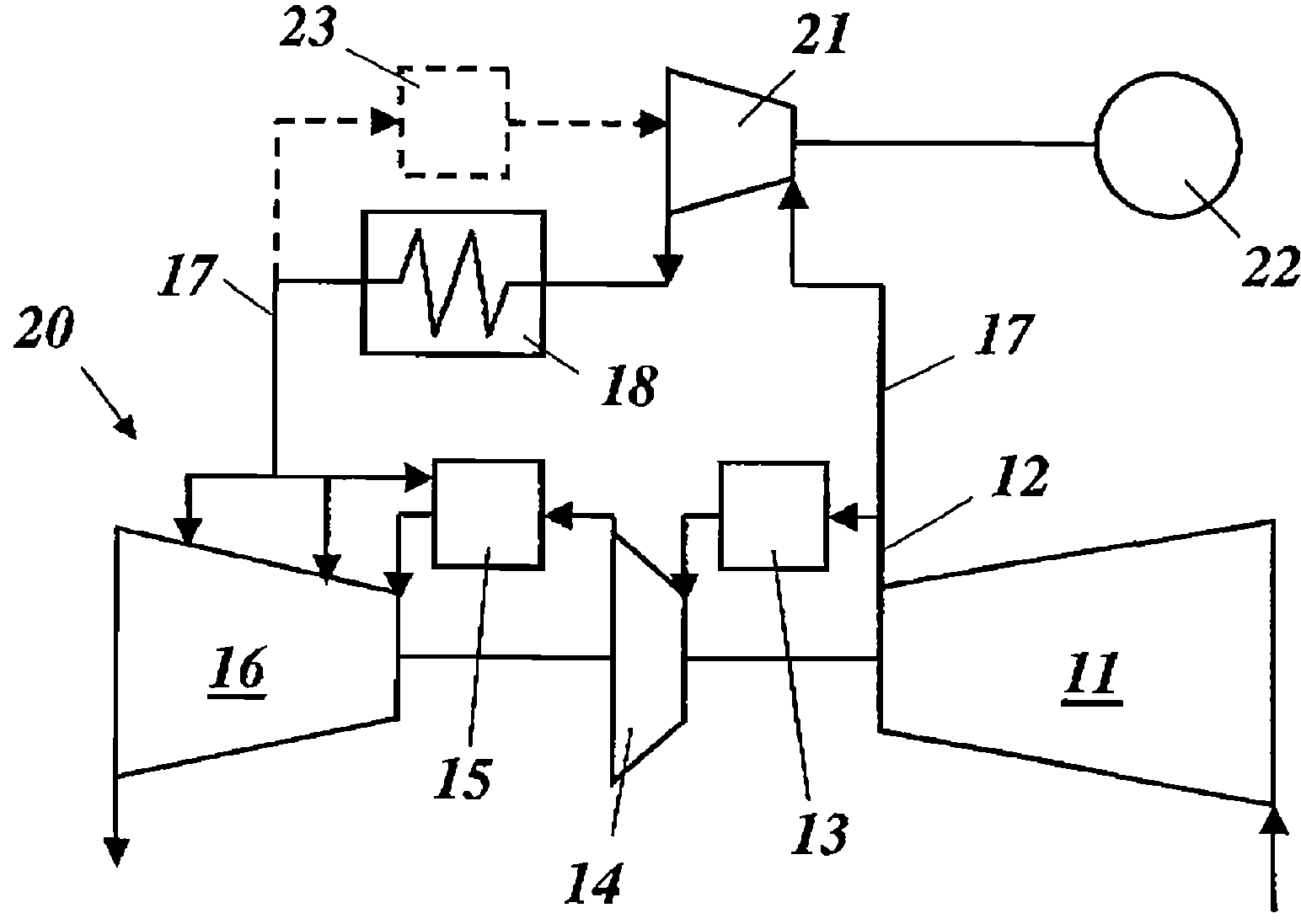
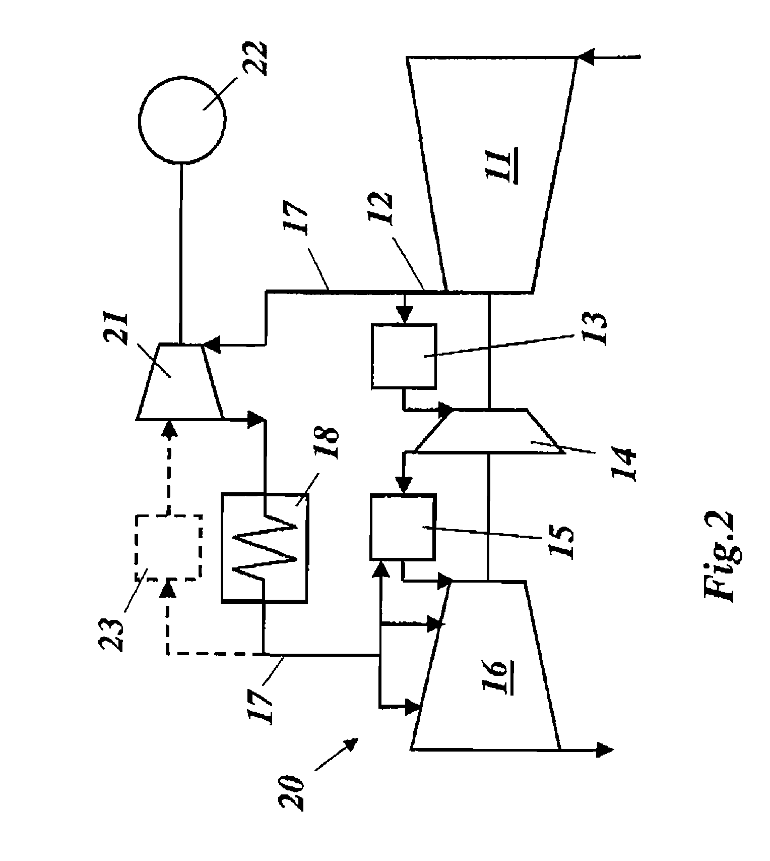
[0018]In FIG. 2, a first exemplary embodiment of a gas turbine 20 according to the invention, in which the exergy occurring as a result of throttling is used in the process, is reproduced in a representation comparable to FIG. 1. Arranged for this purpose in the cooling air duct 17 is an additional regulable turbine 21, the shaft output of which is put to further use. The cooling air is expanded in the turbine 21 to the desired cooling air pressure, which can be adjusted to this value by a regulating device 23. The turbine 21 drives a generator 22, the electrical energy of which can be fed in particular into the power network if the gas turbine is operating in a power generating plant.

[0019]In FIG. 3, a second exemplary embodiment of a gas turbine 30 according to the invention, in which the additional turbine 21 in the cooling air duct 17 drives a gas compressor 24 which compresses gaseous fuel for the fuel chamber 13, is reproduced in a representation comparable to FIG. 1. This pro...


PUM


Abstract

A gas turbine includes a compressor for compressing the combustion air, at least one combustion chamber, in which a fuel is burned while compressed combustion air is supplied, and at least one first turbine arranged downstream of the combustion chamber and in which the hot combustion gases from the combustion chamber are expanded to perform work. Part of the compressed combustion air is branched off, cooled in a cooling air cooler, brought to a lower cooling air pressure by a second turbine and supplied to the gas turbine for cooling purposes.

Description

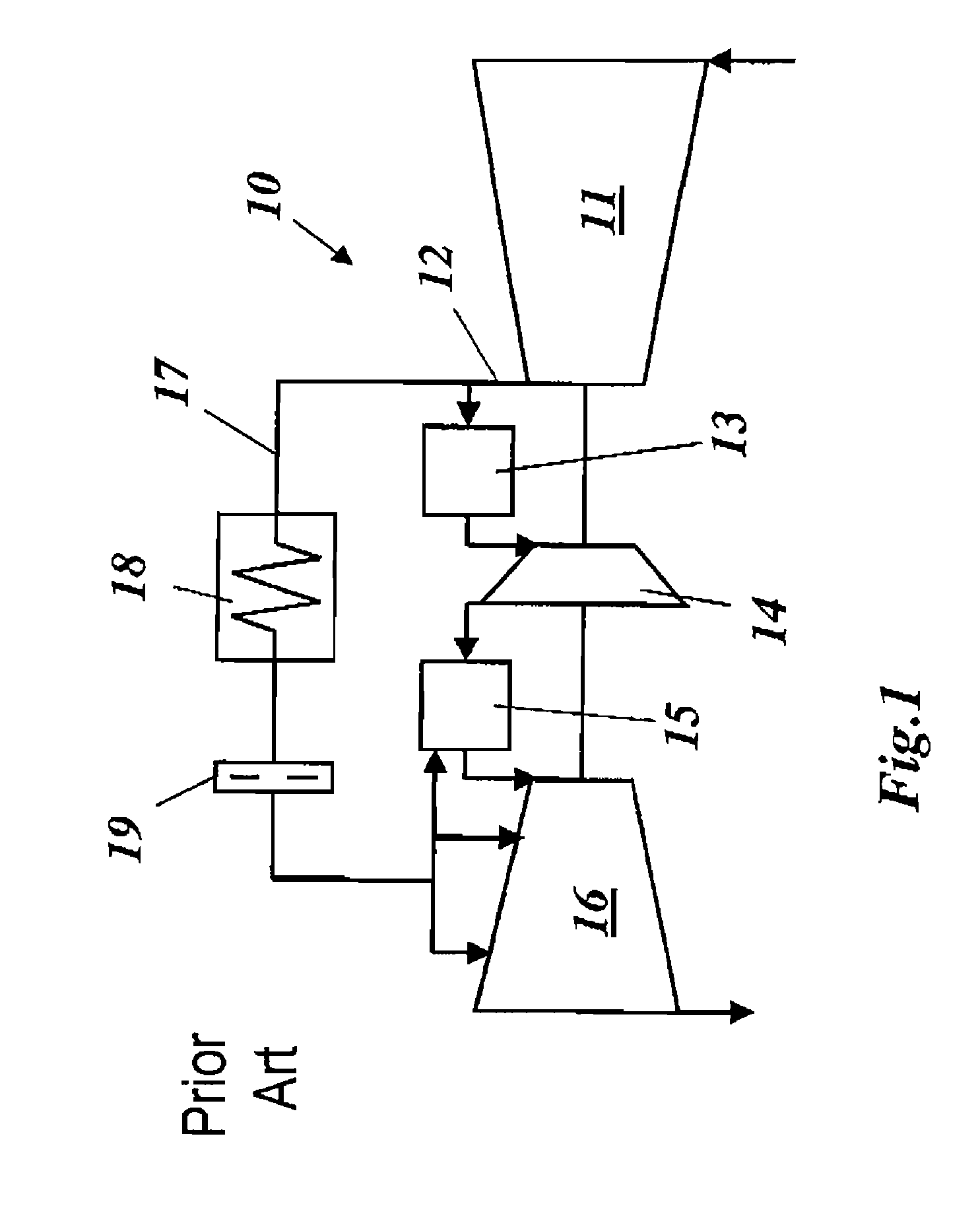
[0001]Priority is claimed to Swiss Patent Application No. CH 01657 / 05, filed on Oct. 12, 2005, the entire disclosure of which is incorporated by reference herein.[0002]The present invention relates generally to the field of gas turbines, and in particular to a gas turbine with cooling air cooling.BACKGROUND[0003]The prior art discloses gas turbines (Field experience with the sequential combustion system of the GT24 / GT26 gas turbine family, ABB Review 5 / 1998, page 12 et seq), in which the cooling air required for the turbine is passed in an MBH30 system through external cooling air ducts from the compressor into a separate cooling air cooler, re-cooled there and then made available to the turbine. The MBH30 system refers here to a secondary air system of the GT24 / GT26 gas turbines, in which air branched off from the compressor after stage 16, which is at a pressure of approximately 20 bar, is used for cooling turbine components (mainly blades). The air exchanged in the cooling air co...

Claims


Application Information

Patent Timeline
Patent Type & Authority Patents(United States)
IPC IPC(8): F02C1/00F02G3/00
CPCF02C3/22F02C7/141F02C7/185F02C7/22Y02E20/16Y02T50/60
Inventor OLMES, SVENREITER, WILHELMZIERER, THOMAS
Owner ALSTOM TECH LTD
Learn More