Method for delivering a multi phase mixture and pump installation

a multi-phase mixture and pump technology, applied in the direction of liquid fuel engines, foam dispersion/prevention, fluid removal, etc., can solve the problems of low head pressure generally not very economical, and achieve the effects of increasing energy content, high gas proportion, and high efficiency

Inactive Publication Date: 2010-10-12
JOH HEINRICH BORNEMANN
View PDF25 Cites 7 Cited by
  • Summary
  • Abstract
  • Description
  • Claims
  • Application Information

AI Technical Summary

Benefits of technology

[0016]A booster pump is arranged in the feed line, so that the separated liquid phase has an increased energy content.
[0017]It has proven advantageous for the displacement pump to be embodied as a screw pump, as screw pumps reliably deliver multi-phase mixtures, in particular with a high proportion of abrasive substances and highly fluctuating gas proportions, and offer advantages in terms of availability.
[0018]For assembly reasons it is advantageous to arrange the ejector pump in or on the well at the end of the suction line; alternatively, it is possible to arrange the ejector pump in a different location, e.g., in the suction line closer to the displacement pump or also in a well distant from the suction line.

Problems solved by technology

2-5 bar are typical for hydrocarbon delivery, e.g., crude oil and natural gas delivery; lower head pressures are generally not very economical because of the volume expansion of the gas proportion and the increasing construction expenditure resulting therefrom.

Method used


Image

  • Method for delivering a multi phase mixture and pump installation
  • Method for delivering a multi phase mixture and pump installation

Examples


Embodiment Construction

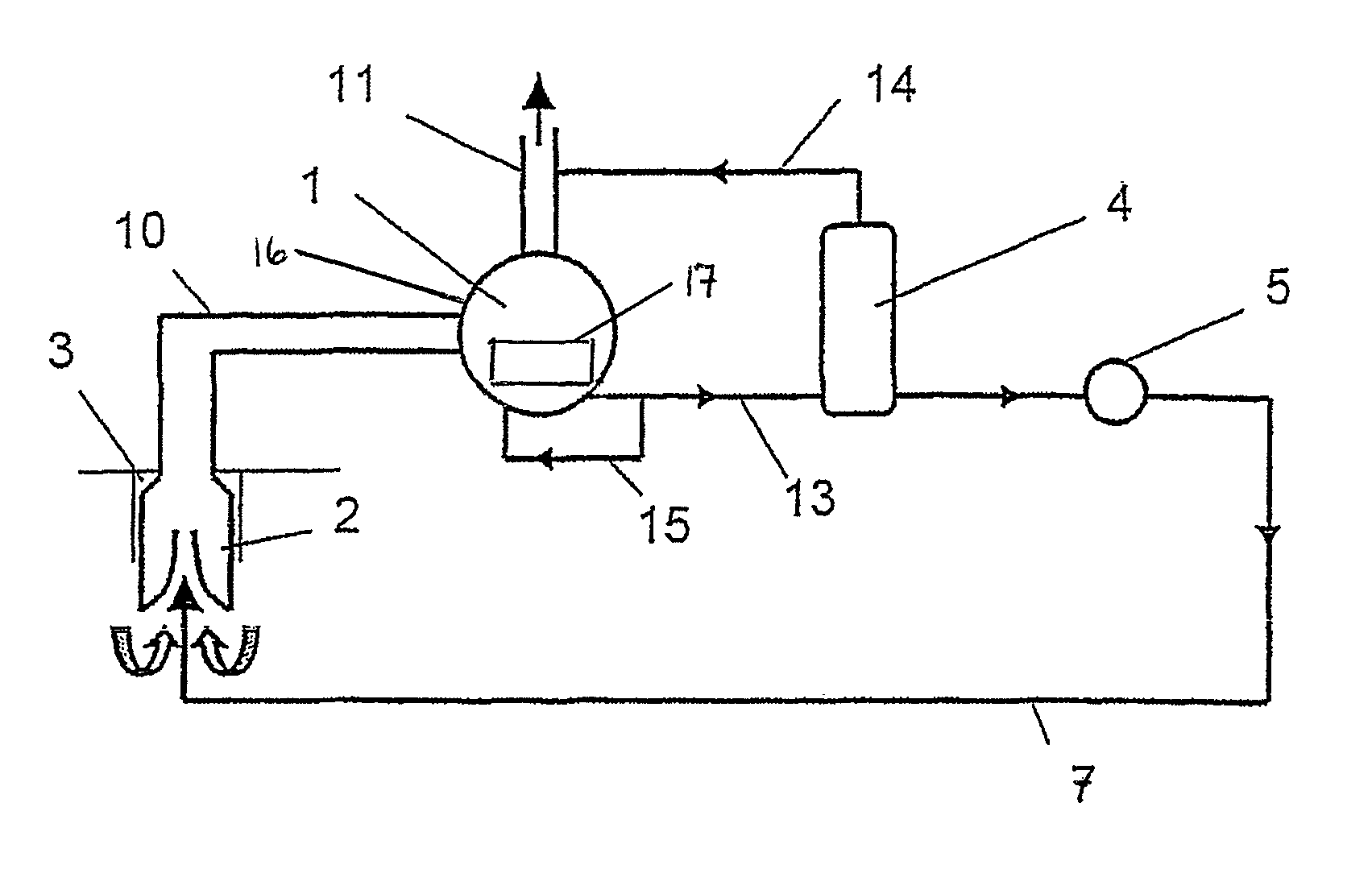
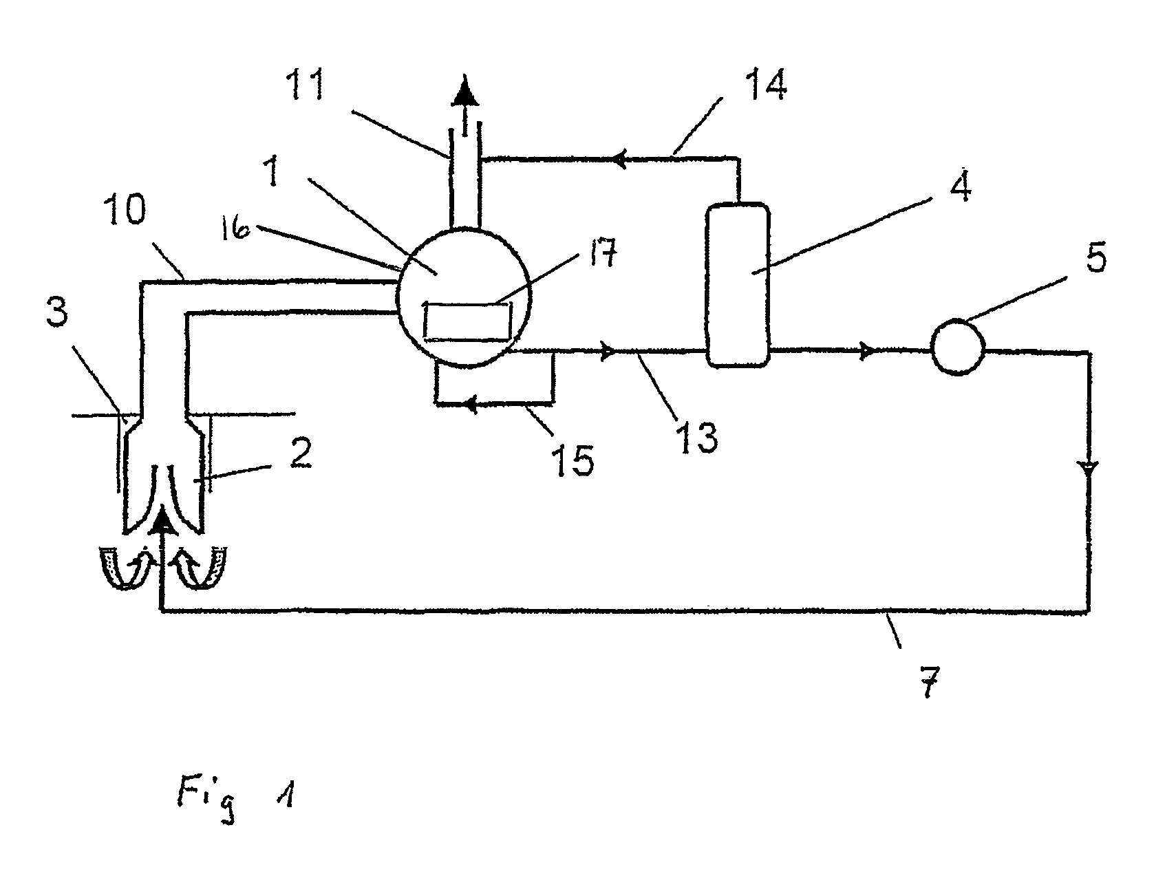
[0020]The core of the pump installation is a displacement pump 1 which is provided as a multi-phase pump and advantageously embodied as a screw pump. A suction line 10 is arranged on the suction side, which discharges into a well 3. An ejector pump 2 is arranged at the end of the suction line 10 within the well. The ejector pump 2 is oriented such that the high-pressure side of the ejector pump 2 faces in the direction of the suction side of the displacement pump 1, in order to load the displacement pump 1 with a prepressure.

[0021]The ejector pump 2, preferably embodied as a jet pump, is fed via a partial liquid flow 13 split off on the pressure side from the displacement pump 1. The partial liquid flow 13 is guided to the high-pressure side of the ejector pump 2 via a feed line 7.

[0022]The partial liquid flow 13 is split off from a separated multi-phase mixture, whereby a separation of the liquid phase and the gas phase takes place within the displacement pump. A predetermined amou...


PUM

PropertyMeasurementUnit
pressureaaaaaaaaaa
volume flowaaaaaaaaaa
partial liquid flowaaaaaaaaaa

Abstract

The object of the invention is to improve delivery of the multi-phase mixture, in particular hydrocarbons from a well, and to limit the free gas volume. According to the invention, this object is attained in that a partial liquid flow (13) is split off on the pressure side from the main delivery flow and guided to the high-pressure side of at least one ejector pump (2) arranged on the suction side as an auxiliary delivery device. The pump installation provides a feed line (7) connecting the pressure chamber of the displacement pump (1) with the high-pressure side of at least one ejector pump (2), whereby the ejector pump (2) is arranged on the suction side in the delivery direction of the displacement pump (1).

Description

FIELD OF THE INVENTION[0001]The invention relates to a method for delivering multi-phase mixtures, in particular hydrocarbons from a well, with a displacement pump through which the multi-phase mixture is pumped, and a pump installation with a displacement pump for delivering multi-phase mixtures with a suction line and a pressure chamber, whereby the suction line discharges in particular into a well.BACKGROUND OF THE INVENTION[0002]Hydrocarbon delivery with multi-phase pumps installed on the surface, generally in the vicinity of the well, is an economical, sufficiently reliable and efficient technology for delivery from weak springs and for increasing the degree of deoiling. Multi-phase pumps are known per se, e.g., from EP 0 699 276 A1, to which reference is made in its entirety, and the disclosure of which is incorporated into the application. Pressure reductions on the solar head to approx. 2-5 bar are typical for hydrocarbon delivery, e.g., crude oil and natural gas delivery; l...

Claims


Application Information

Patent Timeline
Patent Type & Authority Patents(United States)
IPC IPC(8): E21B43/40E21B43/12F04C15/06F04D9/06F04D31/00F04F5/02F04F5/54
CPCE21B43/124E21B43/129F04C15/062F04D9/06F04D31/00F04F5/02F04F5/54F04C11/005F04C2/16F04C2210/24E21B43/121F04C2/107E21B43/12
Inventor BRANDT, JENS UWEROHLFING, GERHARDMUELLER-LINK, DIETRICH
Owner JOH HEINRICH BORNEMANN
Why Eureka
Try Eureka