Hydrogen generation apparatus and method for using same

a hydrogen gas and apparatus technology, applied in the field of chemical arts, can solve the problems of insufficient energy that can be stored in storage or rechargeable batteries, inability to meet the needs of certain applications, and inability to provide compressed hydrogen. , the safety of hydrogen handling and storage is affected

Inactive Publication Date: 2010-10-12
INTELLIGENT ENERGY INC
View PDF63 Cites 19 Cited by
  • Summary
  • Abstract
  • Description
  • Claims
  • Application Information

AI Technical Summary

Problems solved by technology

However, the amount of energy that can be stored in storage or rechargeable batteries is insufficient to meet the need of certain applications.
Merely providing compressed hydrogen is not always a viable option, because of the substantial volume that even a highly compressed gas occupies.
Furthermore, there are safety issues involved with the handling and storage of hydrogen in the compressed gas form or in the liquid form.
Hydrocarbon fuels are somewhat more technically challenging, because hydrocarbon reformation requires relatively higher temperatures, and the simple cracking of hydrocarbons produces a solid residue which is undesirable in a fuel cell application.
It is a drawback of ammonia decomposition that traces of un-reacted ammonia (typically <2000 ppm) remain in the product gas stream.
One of the challenges of utilizing ammonia to produce hydrogen for a fuel cell is that H / AFCs do not tolerate ammonia in the hydrogen feed gas, so the trace amounts of ammonia in the hydrogen produced by an ammonia cracker must be removed before the remaining H2 / N2 mixture is supplied to a fuel cell.
It is a drawback of hydrocarbon reformulation that the actual product is a mixed gas stream that contains substantial amounts of carbon monoxide (CO).
Such additional processes add size, cost, and complexity to a hydrogen generation system, making achieving a compact, low cost, and portable system more difficult.

Method used


Image

  • Hydrogen generation apparatus and method for using same
  • Hydrogen generation apparatus and method for using same
  • Hydrogen generation apparatus and method for using same

Examples


Embodiment Construction

[0051]Particular embodiments of the invention are described below in considerable detail for the purpose for illustrating its principles and operation. However, various modifications may be made, and the scope of the invention is not limited to the exemplary embodiments described.

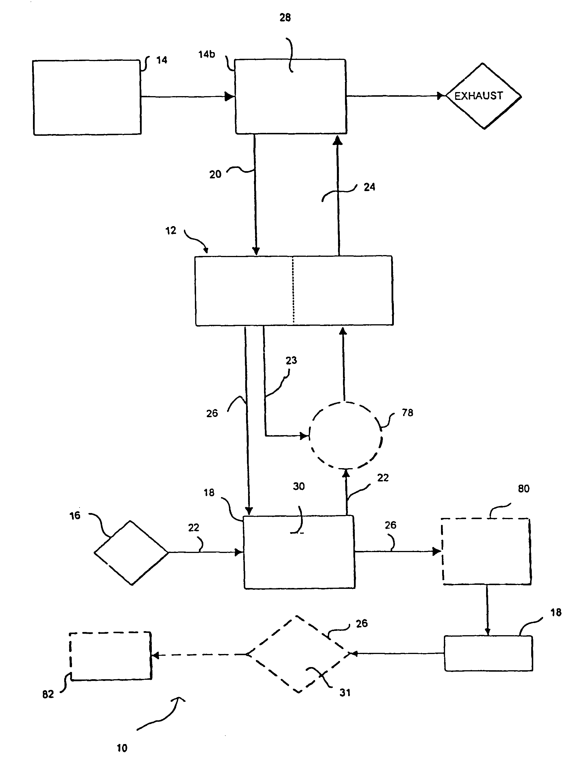
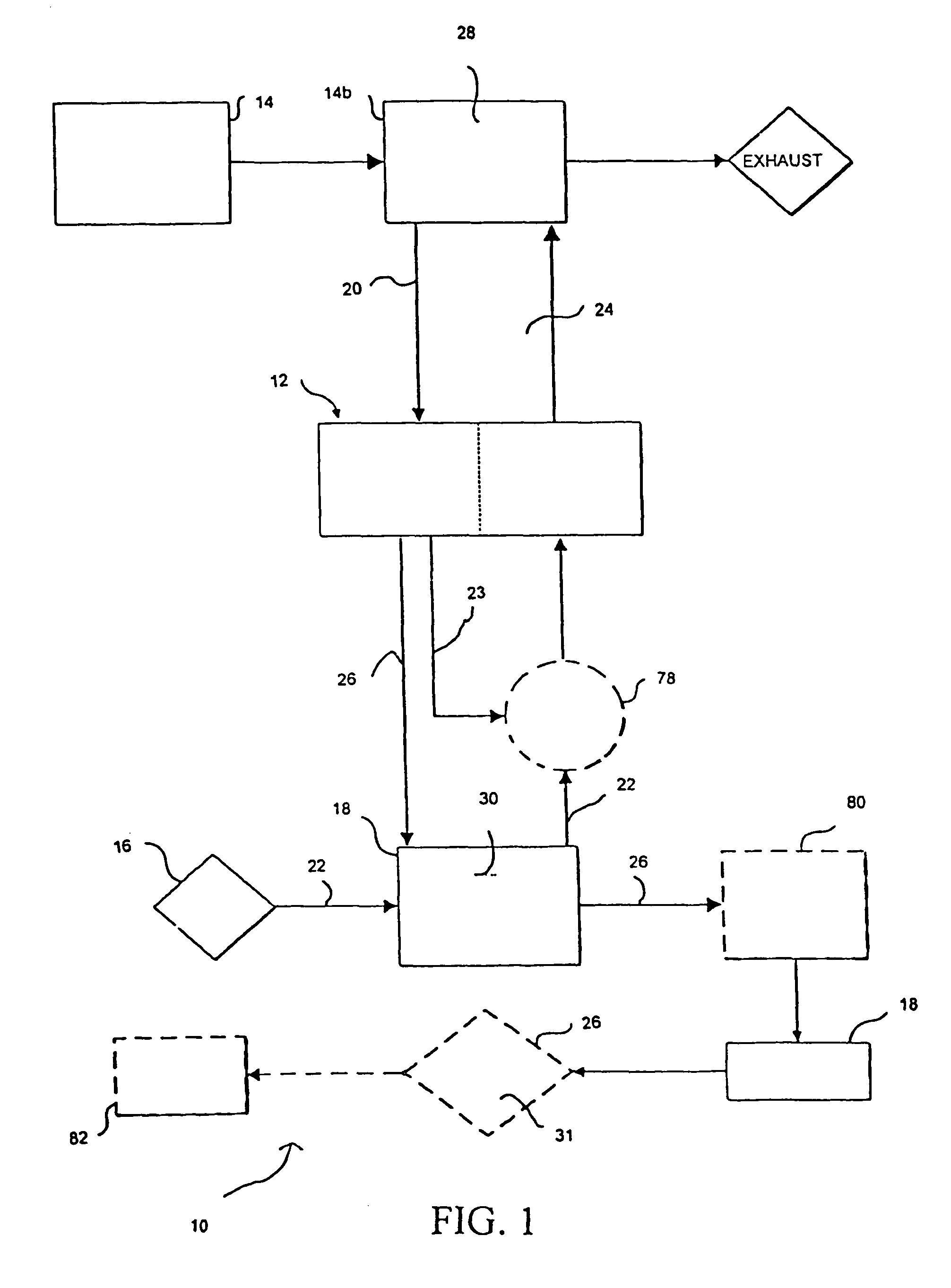
[0052]It is an advantage of the hydrogen generators in accordance with the invention, that with only minor modifications they can be used to generate hydrogen from either ammonia or hydrocarbon fuels. Representative hydrocarbon fuels include, methanol, propane, butane, gasoline, and kerosene fuels, such as JP-8.

[0053]The fuel must be capable of both generating hydrogen and providing thermal energy. In preferred embodiments, the fuel is a liquid fuel. For example, while ammonia is a gas at standard temperature and pressure (STP) conditions, the ammonia is preferably stored in a liquid state. The ammonia is easily liquefied by compression (114 pounds per square inch) and / or by cooling to about −33° C. Similar...


PUM

PropertyMeasurementUnit
widthaaaaaaaaaa
widthaaaaaaaaaa
widthaaaaaaaaaa

Abstract

A compact hydrogen generator for use with fuel cells and other applications includes a hydrogen membrane reactor having a combustion chamber and a reaction chamber. The two chambers are have a fluid connection and a heat exchange relationship with one another. The hydrogen generation apparatus also includes a fuel supply, a fuel supply line for transporting fuel from the fuel supply to the reaction chamber, an oxygen supply, an oxygen supply line for transporting oxygen form the oxygen supply to the combustion chamber, as well as a tail gas supply line for transporting tail gas supply line for transporting tail gases form the reaction chamber, a combustion by-product line for transporting combustion by-products for the combustion chamber, and a reaction product line for transporting hydrogen from the reaction chamber.

Description

CROSS-REFERENCE TO RELATED APPLICATIONS[0001]This application is a U.S. National Phase Application of International Application Number PCT / US02 / 12822, filed Apr. 23, 2002, entitled “Hydrogen generation apparatus and method for using same” by Applicant Mesosystems Technology Inc*-., now expired, which claims the benefit of the prior filing date of U.S. Provisional Patent Application No. 60,286,114, filed Apr. 23, 2001, now expired, the disclosures of which are incorporated herein by reference in their entirety.STATEMENT REGARDING FEDERALLY-SPONSORED RESEARCH OR DEVELOPMENT[0002]This invention was made under contract with the United States Army Research Office, under Contract No. DAAD19-01-C-0015, and the United States Government may have certain rights in the invention.BACKGROUND OF THE INVENTION[0003]1. Field of the Invention[0004]The present invention generally relates to the chemical arts. More particularly, the present invention relates to an apparatus and method for generating h...

Claims


Application Information

Patent Timeline
Patent Type & Authority Patents(United States)
IPC IPC(8): B01J7/02B01J8/00B01J19/24C01B3/04C01B3/24C01B3/32C01B3/38C01B3/50H01M8/06
CPCB01J19/2475B01J19/249C01B3/047C01B3/323C01B3/384C01B3/501H01M8/0612H01M8/0631B01J2219/2453B01J2219/2458B01J2219/2459B01J2219/2462B01J2219/2465B01J2219/2475B01J2219/2479B01J2219/2481B01J2219/2485B01J2219/2486B01J2219/2487B01J2219/2495B01J2219/2497C01B2203/0233C01B2203/0405C01B2203/041C01B2203/042C01B2203/0465C01B2203/047C01B2203/048C01B2203/066C01B2203/0811C01B2203/0822C01B2203/0827C01B2203/0844C01B2203/0866C01B2203/0883C01B2203/1011C01B2203/1035C01B2203/1041C01B2203/1082C01B2203/1205C01B2203/1223C01B2203/1235C01B2203/1241C01B2203/1288C01B2203/146C01B2203/16C01B2203/1604Y02E60/364Y02E60/50Y02E60/36Y02P20/10
Inventor POWELLCALL, CHARLES J.
Owner INTELLIGENT ENERGY INC
Why Eureka
Try Eureka