X-ray detector module with a collimator

a detector module and collimator technology, applied in the direction of radiation intensity measurement, instruments, x/gamma/cosmic radiation measurement, etc., can solve the problems of low absorbance of such materials at relatively high energies, corrupt measurement, and insatiable signal-to-background ratio of known x-ray detector modules, so as to minimize the dead space

Inactive Publication Date: 2010-10-12
DEUTES ELEKTRONEN SYNCHROTRON DESY
View PDF6 Cites 5 Cited by
  • Summary
  • Abstract
  • Description
  • Claims
  • Application Information

AI Technical Summary

Benefits of technology

[0023]By virtue of the construction of the X-ray detector module, which essentially corresponds to the outer contour of the basic carrier in cross section over its entire length, a very compact construction is realized which, moreover, makes it possible to arrange a plurality of X-ray detector modules of this type alongside one another, such that the basic carriers of adjacent X-ray detector modules bear directly against one another, thereby minimizing the dead space between adjacent X-ray detector modules.
[0024]In one advantageous embodiment, each module has a sensor chip having 7 silicon drift detector cells each having the form of an equilateral hexagon, a central cell being surrounded by six cells having the same outer form. The basic carrier preferably likewise has the outer form of an equilateral hexagon which projects slightly beyond the outer edge of the sensor chip. This hexagonal embodiment makes it possible to assemble a plurality of detector modules with their basic carriers bearing directly against one another once again with a central X-ray detector module and six X-ray detector modules arranged around the latter. The arrangement can be extended in any desired manner as necessary.

Problems solved by technology

In other words, the signal-to-background ratio is not satisfactory in the known X-ray detector module.
However, the absorbance of such materials at relatively high energies is so low that large ridge thicknesses would be necessary in the direction of incidence of the X-ray photons.
The disadvantage of heavy elements is that the parasitic fluorescence emerging from them would reach the detector and thus corrupt the measurement.
This widening significantly increases the space available for connecting the conductor tracks to the cores of a cable, which simplifies the production of the connections and reduces their susceptibility to faults, since more space is available for the connections.
In specific applications it is necessary for the cooling tube to be actively cooled, e.g. if the X-ray detector module is arranged in vacuo and heat dissipation by convection into the surrounding air is therefore not possible.

Method used


Image

  • X-ray detector module with a collimator
  • X-ray detector module with a collimator
  • X-ray detector module with a collimator

Examples


Embodiment Construction

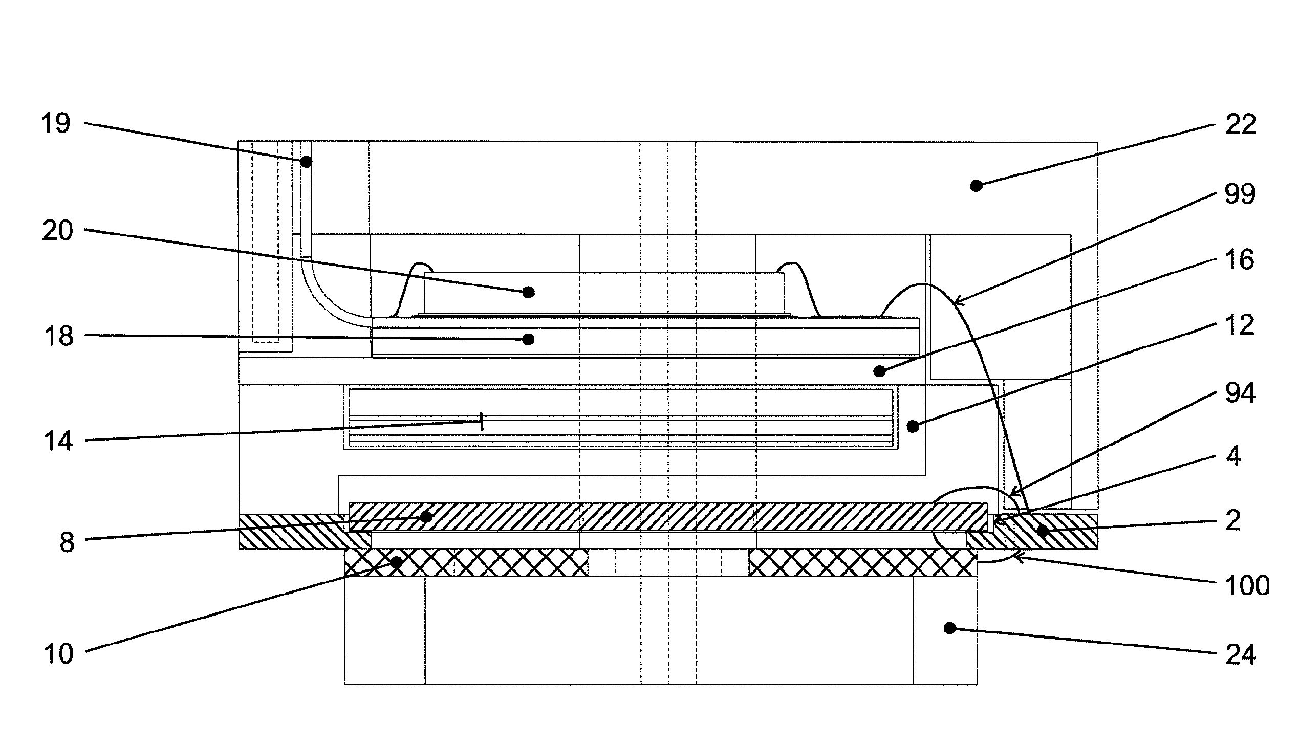
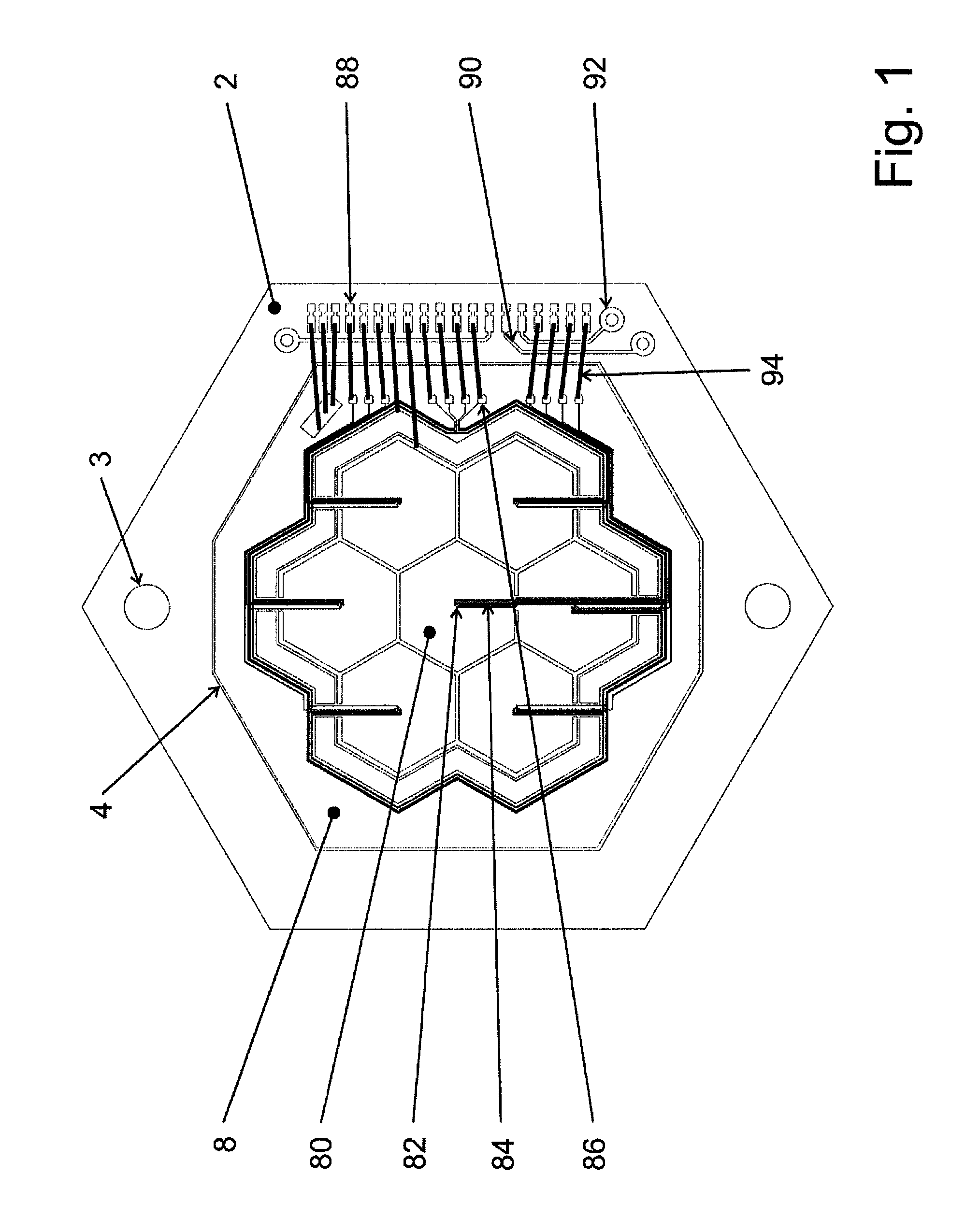
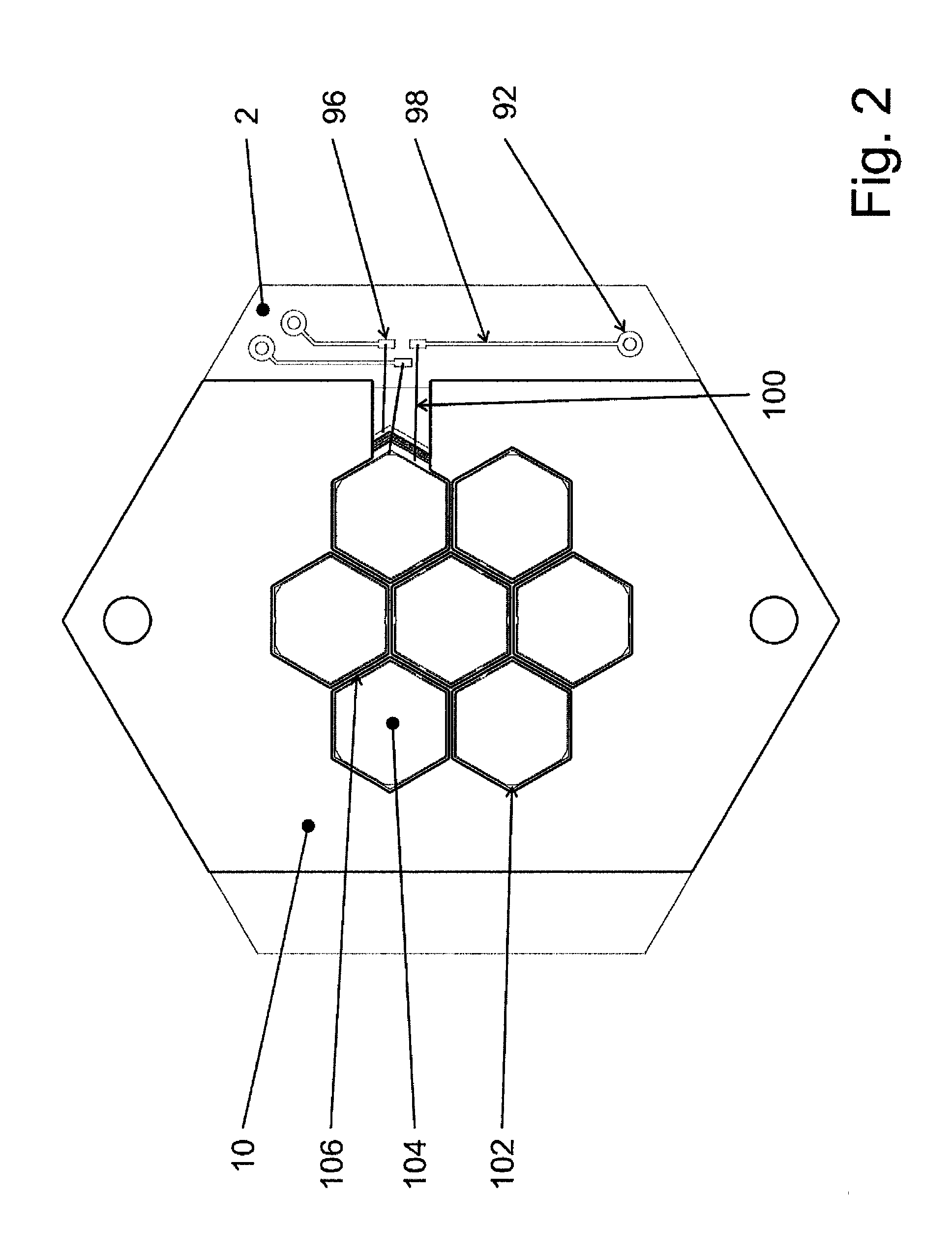
[0032]FIG. 1 shows a plan view of the basic carrier 2 with inserted sensor chip 8 in plan view from the direction of the remaining components of the X-ray detector module. FIG. 2 shows the plan view of the other side of the basic carrier 2, wherein the sensitive detector cells can be seen through the opening of the frame-type basic carrier 2 and the mask 10. The sensor chip 8 is accommodated with an accurate fit in the cutout 4 (see FIG. 3) of the basic carrier 2, whereby accurate positioning of the sensor chip 8 in the construction can be ensured.

[0033]The mask 10 is provided with ridges 106 which project into the opening of the frame-type basic carrier 2 and run over the sensor chip 8. Their course is configured such that they cover the boundary strips of adjacent silicon drift detector cells 80 which adjoin one another. The outer contour of the opening of the mask 10 is shaped in such a way that the outer edge regions of the outer silicon drift detector cells are covered by it, s...


PUM


Abstract

An x-ray detector module comprises a plurality of silicon drift detector cells arranged next to each other on a sensor chip. The sensor chip is arranged in a recess of a frame-shaped base support, such that the sensitive chip surface lies in the opening of the frame-shaped base support. A mask (10) is fixed to the side of the base support (2) opposite to the recess and covers the outer edge areas of external detector cells and ridges above the sensor chip (8) protrude into the opening of the base support (2). The ridges are arranged in such a manner that they cover the defining strips which are adjacent to the detector cells, in order to protect the external edge areas and the defining strips which are covered by the mask (10) counter to the incident x-ray photons.

Description

CROSS REFERENCE OF RELATED APPLICATIONS[0001]This is a National Phase Application pursuant to 37 C.F.R. §371 of International Application No. PCT / EP2006 / 007891, filed 9 Aug. 2006, claiming priority of German Application No. 10 2005 037 860.9 filed 10 Aug. 2005. The disclosure of the International Application and the German application being incorporated in their entirety by reference herein.BACKGROUND OF INVENTION[0002]The present invention relates to an X-ray detector module comprising a plurality of silicon drift detector cells arranged alongside one another on a sensor chip, the sensor chip being accommodated in a cutout of a frame-type basic carrier, such that the sensitive sensor chip surface lies in the opening of the frame-type basic carrier.DISCUSSION OF PRIOR ART[0003]X-ray detector modules of this type are used e.g. in synchrotron X-ray fluorescence analysis (SyRFA) and in X-ray fine structure spectroscopy (XAFS). Both cases here involve determining the energy of individua...

Claims


Application Information

Patent Timeline
Patent Type & Authority Patents(United States)
IPC IPC(8): G01T1/24
CPCH01L27/14618H01L27/14623H01L27/14659H01L2924/0002H01L2924/00
Inventor HANSEN, KARSTENVENZMER, ALEXANDER
Owner DEUTES ELEKTRONEN SYNCHROTRON DESY
Why Eureka
Try Eureka