Transfer rate control method, transmission power control method, transmission power ratio control method, mobile communication system, mobile station, and radio base station

a technology of transmission rate and control method, applied in the field of transmission rate control method, transmission power control method, transmission power ratio control method, can solve the problems of high implementation cost of the network controller, increased process load and process delay in the radio network controller rnc, and difficult control of the transmission rate of uplink user data at a high speed. achieve the effect of increasing the uplink throughpu

Inactive Publication Date: 2010-10-12
NTT DOCOMO INC
View PDF11 Cites 8 Cited by
  • Summary
  • Abstract
  • Description
  • Claims
  • Application Information

AI Technical Summary

Benefits of technology

[0042]The present invention has been made with the foregoing points taken into consideration. An object of the present invention is to provide a transmission rate control method, a transmission power control method, a transmission power ratio control method, a mobile communications system, a mobile station and a base station which make it possible to increase uplink throughput without the uplink channel capacity or the downlink channel capacity running short.
[0043]Another object of the present invention is to realize the “cell common rate control method”, known as a simple transmission rate control method, while holding assignment of hardware resources at as minimum a level as necessary, so as to reduce the hardware resources in use, and to cut back on equipment costs.
[0053]A tenth aspect of the present invention is summarized as a radio base station which receives uplink user data transmitted from a mobile station, wherein the radio base station is configured to assign uplink radio resources in order that the radio base station can receive the uplink user data, at an initial transmission power which is informed from a network or an initial transmission power which has been already informed from the network; and increase the uplink radio resources to be assigned, each time the transmission rate of the uplink user data is increased on a basis of a increase rule of increasing the transmission rate which is beforehand determined.

Problems solved by technology

In the conventional mobile communications system however there is a problem that it is hard to control change of transmission rate of uplink user data at a high speed (for example, at a speed of approximately 1 microsecond to 100 microseconds), because the radio network controller RNC usually controls many radio base stations NodeB jointly, and it is assumed that process loads and process delays in the radio network controller RNC are increased.
In the mobile communications system, there is another problem that implementation costs of the apparatus and operating costs of the network run high, even though the change of transmission rate of uplink user data can be controlled at a high speed.
Therefore, there is a problem of making hardware configuration or software configuration of the radio base station NodeB more complicated, or a problem of prolonging a time needed to process the reception of the uplink user data.
Furthermore, in the conventional “Time & Rate Control”, every mobile station UE located in the same cell is configured to transmit its uplink control data to the radio base station NodeB Therefore, there is a problem that the uplink channel capacity runs short.
Therefore, there is a problem that the downlink channel capacity runs short as well.
In addition, in the conventional “Time & Rate Control”, there is a problem that, when a reception error occurs in downlink control data, uplink radio resources which have been used to transmit uplink control data comes in vein.
Therefore, there is a problem that the downlink channel capacity runs short.
However, there is a problem that an disagreement between a transmission rate of uplink user data recognized by the radio base station NodeB and a transmission rate of the uplink user data recognized by the mobile station UE occurs, and, in some cases, the radio base station NodeB fails to receive uplink user data transmitted by the mobile station UE, or a transmission rate of uplink user data which has been assigned by the radio base station NodeB is not implemented and the use of the u-link radio resources for the transmission comes in vain, in the case where a bit error occurs in such a command.
Furthermore, in the conventional “Rate Control”, there is a problem that, if the radio base station NodeB controls the maximum allowable transmission rate, the maximum allowable transmission power or the maximum allowable transmission power ratio of uplink user data by transmitting a single UP command / Down command to all the mobile stations UE throughout the cell, this control hinders the assignment of the uplink radio resources among the mobile stations UE from being equal.
As a result, there is a problem that the assignment of uplink radio resources is not equal between the mobile stations.
Furthermore, in the conventional “Rate Control”, when a method of informing the entire cell of the maximum allowable transmission rate, the maximum allowable transmission power or the maximum allowable transmission power ratio of uplink user data (or the coefficients used for calculating the maximum allowable transmission rate, the maximum allowable transmission power or the maximum allowable transmission power ratio of uplink user data) is used (hereinafter, referred to as a “cell common rate control method”), there is a problem as follows.
As a result, this increases equipment costs.
In other words, since all the mobile stations UE connected to the cell use the maximum allowable transmission rate, the maximum allowable transmission power or the maximum allowable transmission power ratio (or the coefficients for calculating the maximum allowable transmission rate, the maximum allowable transmission power or the maximum allowable transmission power ratio) which is common among the mobile stations UE, in the cell common rate control method, there is a problem that the radio base station NodeB needs to make the same amount of hardware resources available for a mobile station UE with a smaller amount of traffic as for a mobile station UE with a larger amount of traffic.
The conventional “Autonomous Transmission” is not capable of controlling a maximum allowable transmission rate of uplink user data by use of Layer 1 or MAC sublayer.
As a result, it is not expected that the conventional “Autonomous Transmission” improves the effective use of uplink radio resources by itself.

Method used


Image

  • Transfer rate control method, transmission power control method, transmission power ratio control method, mobile communication system, mobile station, and radio base station
  • Transfer rate control method, transmission power control method, transmission power ratio control method, mobile communication system, mobile station, and radio base station
  • Transfer rate control method, transmission power control method, transmission power ratio control method, mobile communication system, mobile station, and radio base station

Examples


first embodiment

A Configuration of a Mobile Communications System According to the Present Invention

[0091]Descriptions will be provided for a configuration of a mobile communications system according to a first embodiment present invention by referring to FIGS. 6 to 25. The mobile communications system according to this embodiment is designed for the purpose of improving communication performance such as channel capacity and communication quality. In addition the mobile communications system according to this embodiment can be applied to the “W-CDMA” and the “CDMA2000” which are the third generation mobile communications systems.

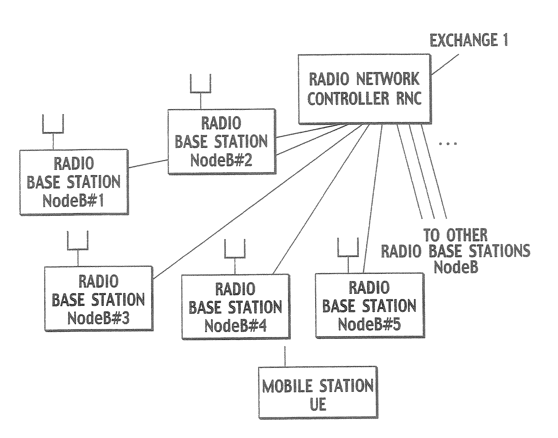
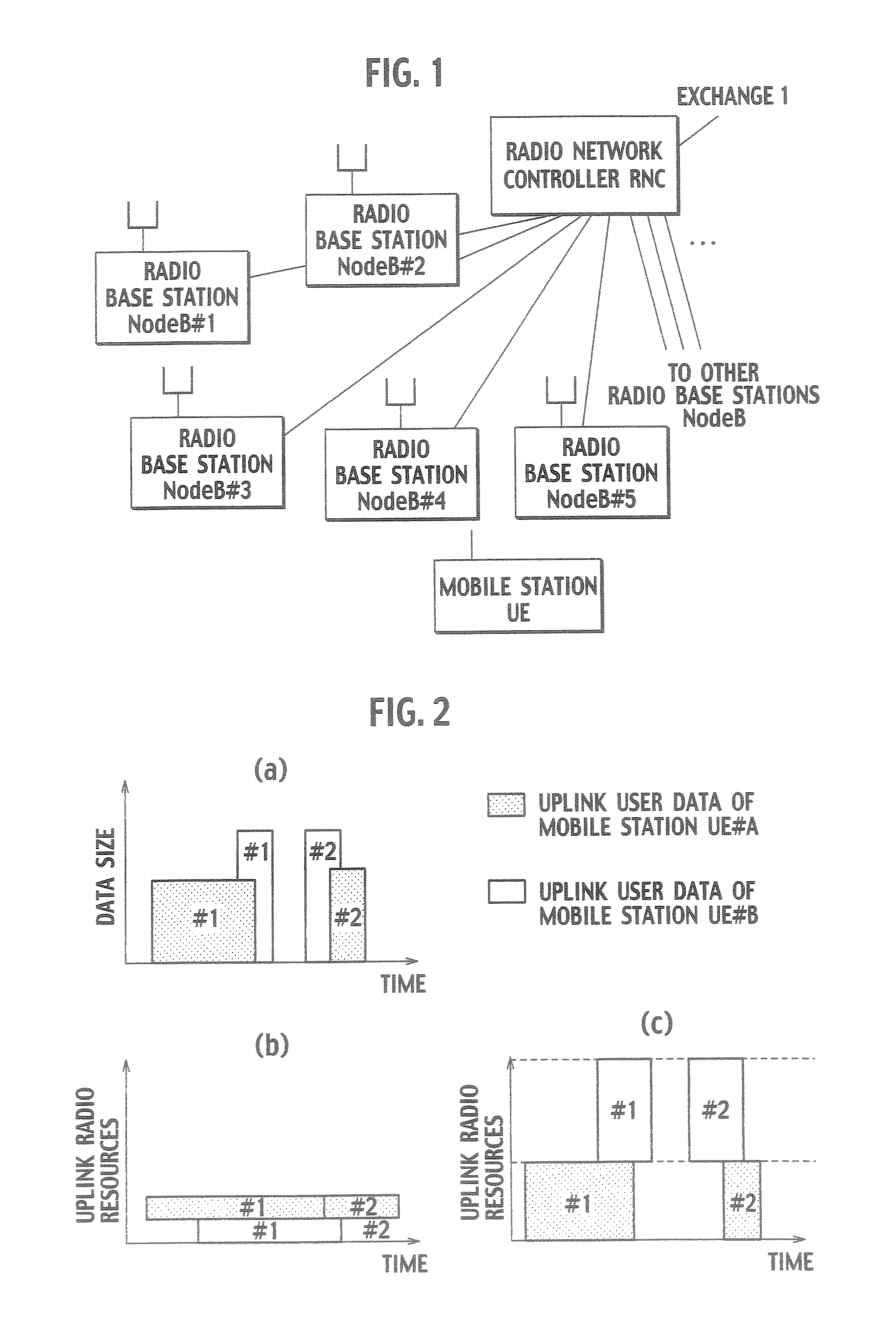
[0092]As shown in FIG. 6, the mobile communications system according to this embodiment is configured of an exchange 1, a radio network controller RNC, a radio base station NodeB and mobile stations UE. The mobile stations UE#1 to UE#3 shown in FIG. 6 transmit and receive user data to be transmitted by use of their respective dedicated physical channels #1 to #3 which have ...

second embodiment

the Present Invention

[0215]A mobile communications system according to a second embodiment of the present invention is the same as the mobile communications system according to the first embodiment except that, as shown in FIGS. 28 to 30, the transmission power of uplink user data is controlled instead of the transmission rate of the uplink user data.

[0216]In the case of this embodiment, as shown in FIG. 28, the E-TFC selector unit 134b in the MAC-e function unit 13c is configured to define a “transmission power level” of each mobile station UE instead of the “rate level” as shown in FIG. 14, and to classify the mobile station UE according to the transmission power level thus defined.

[0217]The transmission power of this case may be a total sum of transmission powers respectively of all the dedicated physical channels of a mobile station UE, or may be transmission power of a channel (E-DPDCH) for the mobile station UE to transmit uplink user data.

[0218]It should be noted that, in thi...

third embodiment

the Present Invention

[0220]A mobile communications system according to a third embodiment of the present invention is the same as the mobile communications system according to the first embodiment except that, as shown in FIGS. 31 to 33, the transmission power ratio of uplink user data is controlled instead of the transmission rate of the uplink user data.

[0221]In this respect, the transmission power ratio of the uplink user data is a ratio of a transmission power of an enhanced dedicated physical data channel (F-DPDCH) of the uplink user data to a transmission power of a dedicated physical data channel (DPCCH) of the uplink user data.

[0222]In this embodiment, as shown in FIG. 31, the E-TFC selector unit 134b in the MAC-e function unit 13c is configured to define the “transmission power ratio level” of each mobile station UE, instead of the “rate level” as shown in FIG. 14, and to classify the mobile stations UE according to the transmission power ratio level thus defined.


PUM


Abstract

The present invention relates to a transmission rate control method of controlling a transmission rate of uplink user data to be transmitted from a mobile station to a radio base station. The method includes: starting to transmit at the mobile station, the uplink user data at an initial transmission rate which is informed from a network or an initial transmission rate which has been already informed from the network; and increasing at the mobile station the transmission rate of the uplink user data, up to a predetermined transmission rate, on a basis of a increase rule of the transmission rate which is beforehand determined.

Description

TECHNICAL FIELD[0001]The present invention relates to a transmission rate control method of controlling a transmission rate of uplink user data to be transmitted from a mobile station to a radio base station, and to a mobile communications system, a mobile station and a radio base station which realize the transmission rate control method.[0002]In addition, the present invention relates to a transmission power control method of controlling transmission power of uplink user data to be transmitted from a mobile station to a radio base station, and to a mobile communications system, a mobile station and a radio base station which realize the transmission power control method.[0003]Furthermore, the present invention relates to a transmission power ratio control method of controlling a transmission power ratio of uplink user data to be transmitted from a mobile station to a radio base station, and relates to a mobile communications system, a mobile station and radio base station, which r...

Claims


Application Information

Patent Timeline
Patent Type & Authority Patents(United States)
IPC IPC(8): H04B7/00H04W28/22H04L29/08H04W52/14H04W52/26H04W52/36
CPCH04L1/0002H04W28/22H04L67/32H04L1/0026H04L1/1803H04L67/04H04L67/60H04L47/25
Inventor USUDA, MASAFUMIUMESH, ANILNAKAMURA, TAKEHIRO
Owner NTT DOCOMO INC
Why Eureka
Try Eureka