Installation apparatus

a technology for installing apparatus and wire harnesses, which is applied in the direction of roofs, contact members penetrating/cutting insulation/cable strands, coupling device connections, etc., can solve the problems of high time and labor requirements for fixing operation, and insufficient strength of the upper wall portion to withstand a load applied from the upper side, so as to prevent damage to the wire harness received in the case. , the effect of increasing the strength of the cas

Inactive Publication Date: 2010-10-19
YAZAKI CORP
View PDF17 Cites 20 Cited by
  • Summary
  • Abstract
  • Description
  • Claims
  • Application Information

AI Technical Summary

Benefits of technology

[0010]This invention has been made in view of the above circumstances, and an object of the invention is to provide an installation apparatus in which the strength of a case for receiving a wire harness can be increased, thereby preventing damage of the wire harness received in the case, and besides a compact and lightweight design of the installation apparatus can be achieved.

Problems solved by technology

Therefore, it is feared that the strength of this upper wall portion is not sufficient to withstand a load applied from the upper side.
And besides, it is feared that the upper wall, when deformed, contacts the wire harness received within the case 103, and damages this wire harness.
Much time and labor are required for this fixing operation, and besides it is feared that the weight of the installation apparatus 101 is increased by weights of flange portions and fastening members used for welding and fastening purposes.

Method used


Image

  • Installation apparatus
  • Installation apparatus
  • Installation apparatus

Examples


Embodiment Construction

[0044]A preferred embodiment of an installation apparatus of the present invention will now be described in detail with reference to the drawings.

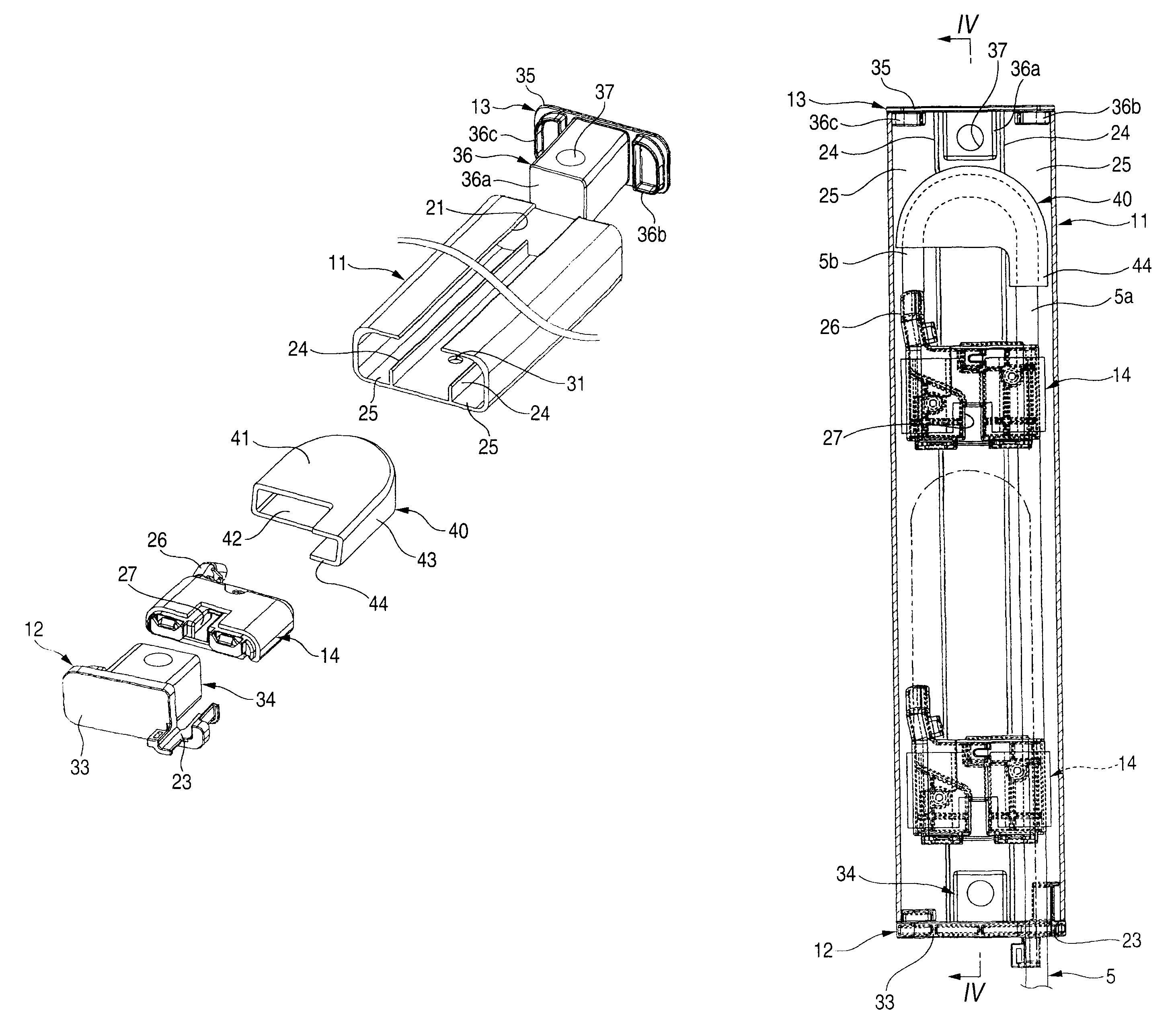
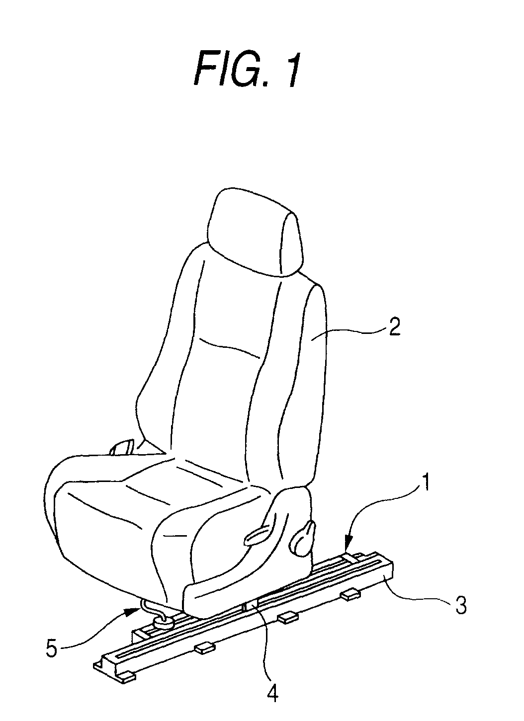
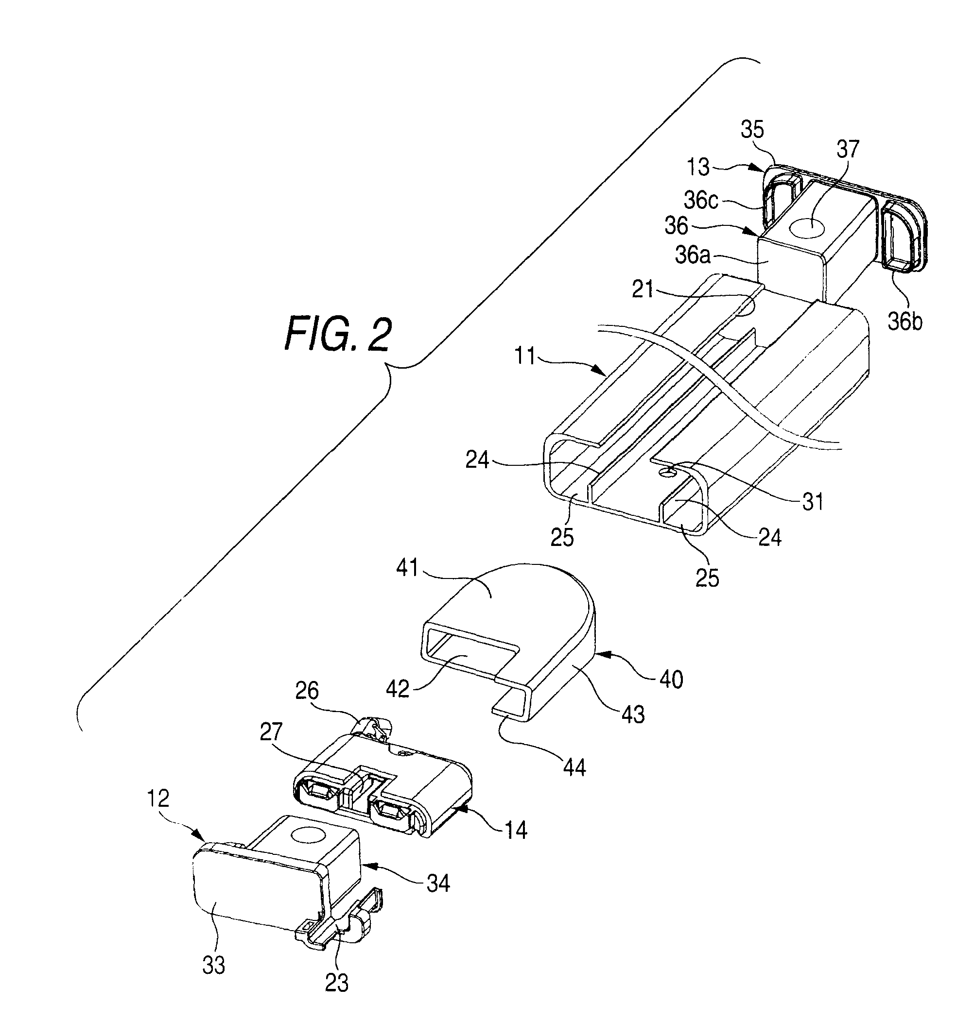
[0045]FIG. 1 is a perspective view showing one preferred embodiment of the installation apparatus of the invention applied to a slide seat for a vehicle, FIG. 2 is an exploded, perspective view of the installation apparatus of FIG. 1, FIG. 3 is a plan view of the installation apparatus of FIG. 1, FIG. 4 is a cross-sectional view taken along the line IV-IV of FIG. 3, FIG. 5 is a perspective view of a slider of FIG. 2, and FIG. 6 is a cross-sectional view taken along the line VI-VI of FIG. 5.

[0046]As shown in FIG. 1, the installation apparatus 1 of this embodiment is applied to the slide seat (movable structural body) 2 for the vehicle. A guide rail 3 is mounted on a vehicle body (fixed structural body; see FIG. 4) 6, and extends in a forward-rearward direction of the vehicle body 6. The slider 4 is mounted on a bottom surface of the slide s...


PUM

PropertyMeasurementUnit
lengthaaaaaaaaaa
semi-circular shapeaaaaaaaaaa
electric poweraaaaaaaaaa

Abstract

An installation apparatus for installing a wire harness over a fixed structural body and a movable structural body which is slidingly movable to the fixed structural body, the installation apparatus includes a case that receives the wire harness such that the wire harness extends in a sliding direction of sliding movement of the movable structural body, and is folded back into a generally U-shape; and a slider that holds a distal end-side portion of the wire harness extending from the folded-back portion toward a distal end of the wire harness, and is slidably supported on the case so as to move in the sliding direction of the movable structural body, and is operatively connected to the movable structural body so as to move in accordance with the sliding movement of the movable structural body. A slit is formed in a wall of the case, and extends in the sliding direction of the movable structural body. The slit is arranged so as to intersect the folded-back portion of the wire harness in view of above of the wall in which the slit is formed. The distal end-side portion of the wire harness is led out from the case through the slit.

Description

BACKGROUND OF THE INVENTION[0001]This invention relates to an installation apparatus for installing a wire harness over a fixed structural body (such for example as a vehicle body of an automobile) and a movable structural body (such as a slide seat or a slide door) movable relative to the vehicle body.[0002]For example, an electrically-operated auxiliary equipment such as an electrically-operated slide mechanism is contained in a slide seat and a slide door of a vehicle such as an automobile. A wire harness is installed over a vehicle body and the slide seat or the slide door in order to supply electric power to such auxiliary equipment. FIG. 7 shows one known related installation apparatus for installing a wire harness over a vehicle body and a slide door (see, for example, JP-A-2005-59745).[0003]As shown in FIG. 7, the installation apparatus 101 disclosed in Patent Literature 1 comprises a box-like case 103 (made of a synthetic resin) receiving the wire harness 102 folded back in...

Claims


Application Information

Patent Timeline
Patent Type & Authority Patents(United States)
IPC IPC(8): B23P11/00H01R4/24
CPCB60N2/0224B60N2/0702B60N2/0725B60N2/0732B60R16/0215Y10T29/4984B60N2002/0264Y10T29/53213Y10T29/53243Y10T29/49904B60N2/0264
Inventor TERADA, TOMOYASU
Owner YAZAKI CORP
Why Eureka
Try Eureka