Integrated urea box assembly

A urea tank and integrated technology, which is applied in the field of urea tanks, can solve problems such as unfavorable device service life, poor line cleanliness, car body damage, etc., and achieve the effects of safe use, clean line built-in, and increased service life

Inactive Publication Date: 2020-12-18
山东艾泰克环保科技股份有限公司
View PDF9 Cites 0 Cited by
  • Summary
  • Abstract
  • Description
  • Claims
  • Application Information

AI Technical Summary

Problems solved by technology

[0003] A Chinese patent discloses an integrated urea tank assembly (authorized announcement number CN207583471U). Compared with the prior art, this patented technology considers structural strength and light weight. However, the integrated urea tank assembly currently on the market In general, the pump line is external, without a protective structure, and the cleanliness of the line is poor. It is easy to accidentally touch the line and cause the connection to be interrupted. Rats and other animals eat the line, resulting in damage. When the vehicle runs for a long time, a large amount of dust will accumulate. The heat dissipation of the pump is affected, and the sun and rain accelerate the aging of the pump, which is not conducive to the service life of the device. The liquid filling port of most devices is exposed outside the device, which leads to people who maliciously destroy the urea tank. Theft and addition of other substances lead to damage to the car body, which is not conducive to the safety of the device, and cannot be used to prevent theft. Most of them do not have an independent display structure for sensing information, and it is not convenient to watch the operation of the device during maintenance. When the device sensor and the interior of the car body When the display is disconnected, you cannot watch the information and add liquid in time for maintenance

Method used


Image

  • Integrated urea box assembly
  • Integrated urea box assembly
  • Integrated urea box assembly

Examples


Embodiment Construction

[0020] The following will clearly and completely describe the technical solutions in the embodiments of the present invention with reference to the accompanying drawings in the embodiments of the present invention. Obviously, the described embodiments are only some, not all, embodiments of the present invention. Based on the embodiments of the present invention, all other embodiments obtained by persons of ordinary skill in the art without making creative efforts belong to the protection scope of the present invention.

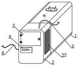
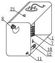
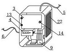
[0021] see Figure 1~5 , in an embodiment of the present invention, an integrated urea tank assembly includes a liquid tank 1, a pump protection case 2 is welded on the front surface of the liquid tank 1, a controller 4 is installed on the front surface of the pump protection case 2, and the pump A liquid pump 9 is installed on the inner lower surface of the machine protection box 2, and an inspection door 3 is installed on the front surface of the upper end o...


PUM


Abstract

The invention relates to the technical field of urea tanks, in particular to an integrated urea box assembly. The assembly comprises a liquid box, a pump machine protection box is welded to the frontsurface of the liquid box, a controller is installed on the front surface of the pump machine protection box, and a liquid pump is installed on the lower surface of the interior of the pump machine protection box. An access door is rotationally installed on the front surface of the upper end of the pump machine protection box, a liquid spraying pipe is arranged on the upper surface of the pump machine protection box, a liquid guide pipe is installed at the lower end of the interior of the liquid box, a filter head is installed at the rear end of the liquid guide pipe, and a liquid level sensorand a temperature sensor are installed in the liquid box. An exhaust valve is mounted on the upper surface of the liquid box. The assembly is provided with a protection structure, adhesion of dust isreduced, the problem that aging of the pump is accelerated due to sun exposure and rain drenching is avoided, a liquid adding opening is locked in the protection structure, theft prevention can be achieved, and a sensing information independent display structure is arranged.

Description

technical field [0001] The invention relates to the technical field of urea tanks, in particular to an integrated urea tank assembly. Background technique [0002] The urea tank is the urea storage tank, also known as the urea tank. The tank is filled with urea solution. It is mainly used for trucks and buses. After the vehicle exhaust passes through the urea tank, the emission will meet the National IV standard. The National IV and Euro IV emission standards implemented in 2008 Standard, diesel engine emission reduction system needs to use urea aqueous solution. The urea tank is used to store urea aqueous solution. In order to reduce the emission of harmful gas NOX in automobiles, SCR selective reduction technology is widely used in the world. The principle of SCR exhaust gas treatment is to use urea The aqueous solution reacts with nitrogen oxides NOX to produce non-polluting nitrogen and water. [0003] A Chinese patent discloses an integrated urea tank assembly (authori...

Claims


Application Information

Patent Timeline
Patent Type & Authority Applications(China)
IPC IPC(8): F01N3/20
CPCF01N3/2066F01N2610/02F01N2610/1406F01N2610/1426F01N2610/144F01N2610/1466F01N2610/148
Inventor 鞠焕鹏
Owner 山东艾泰克环保科技股份有限公司
Why Eureka
Try Eureka