Filter device

a filter device and filter technology, applied in the direction of filtration separation, moving filter element filter, separation process, etc., can solve the problems of high production cost, complicated maintenance, and hydrocarbon oil fouling during operation, and achieve the effect of low production, installation and maintenance cos

Active Publication Date: 2010-10-19
HYDAC FILTERTECHNIK GMBH
View PDF12 Cites 7 Cited by
  • Summary
  • Abstract
  • Description
  • Claims
  • Application Information

AI Technical Summary

Benefits of technology

[0004]An object of the present invention is to provide an improved filter device meeting the above described requirements for their operation in a space-saving and reliable manner with low production, installation and maintenance costs.
[0005]This object is achieved by a filter device having connecting means provided with at least one longitudinally displaceable blocking part which blocks the fluid connection in a blocking position. After displacement into the open position, the fluid connection is cleared. A blocking slide valve is implemented making it possible to block or clear the fluid connections with only a brief actuation process to change the filter element for the used filter medium and to re-use the filter element stored in the filter housing for the filtration tasks under consideration. Since it can be seen from the outside, the operating position of the blocking slide valve is also evident to an operator, which operating position the filter device currently assumes. Based on the configuration of the blocking part as a longitudinally displaceable blocking slide valve, it requires little installation space and can be easily used for cramped installation conditions. The linear displacement motion of the blocking part can be mechanically controlled easily and effectively. This arrangement helps reduce the production, installation and maintenance costs. Operation of the connecting device as the blocking and clearance means, even under difficult ambient conditions, is achieved.

Problems solved by technology

Hydraulic oil is fouled during installation and when the respective hydraulic system is started up.
In addition to this initial fouling, fouling during operation can occur, for example by penetration of dirt at the hydraulic tank due to inadequate tank ventilation, pipe penetrations, piston rod seals, and the like.
The rotary slide valve parts, as a component of a connecting means between the filter housing and the fluid means, are not only expensive to produce and complicated to maintain, but also entail the danger that correspondingly large amounts of fluid will emerge from the fluid means as a leaking oil flow.
This leakage leads to fouling problems in the vicinity.
These solutions are also prone to failure in operation.
In this regard, they are less reliable, since an operator often has problems at the assumed position of the rotary slide valve parts in recognizing whether they are in their blocking or in their open position.

Method used


Image

  • Filter device
  • Filter device
  • Filter device

Examples


Embodiment Construction

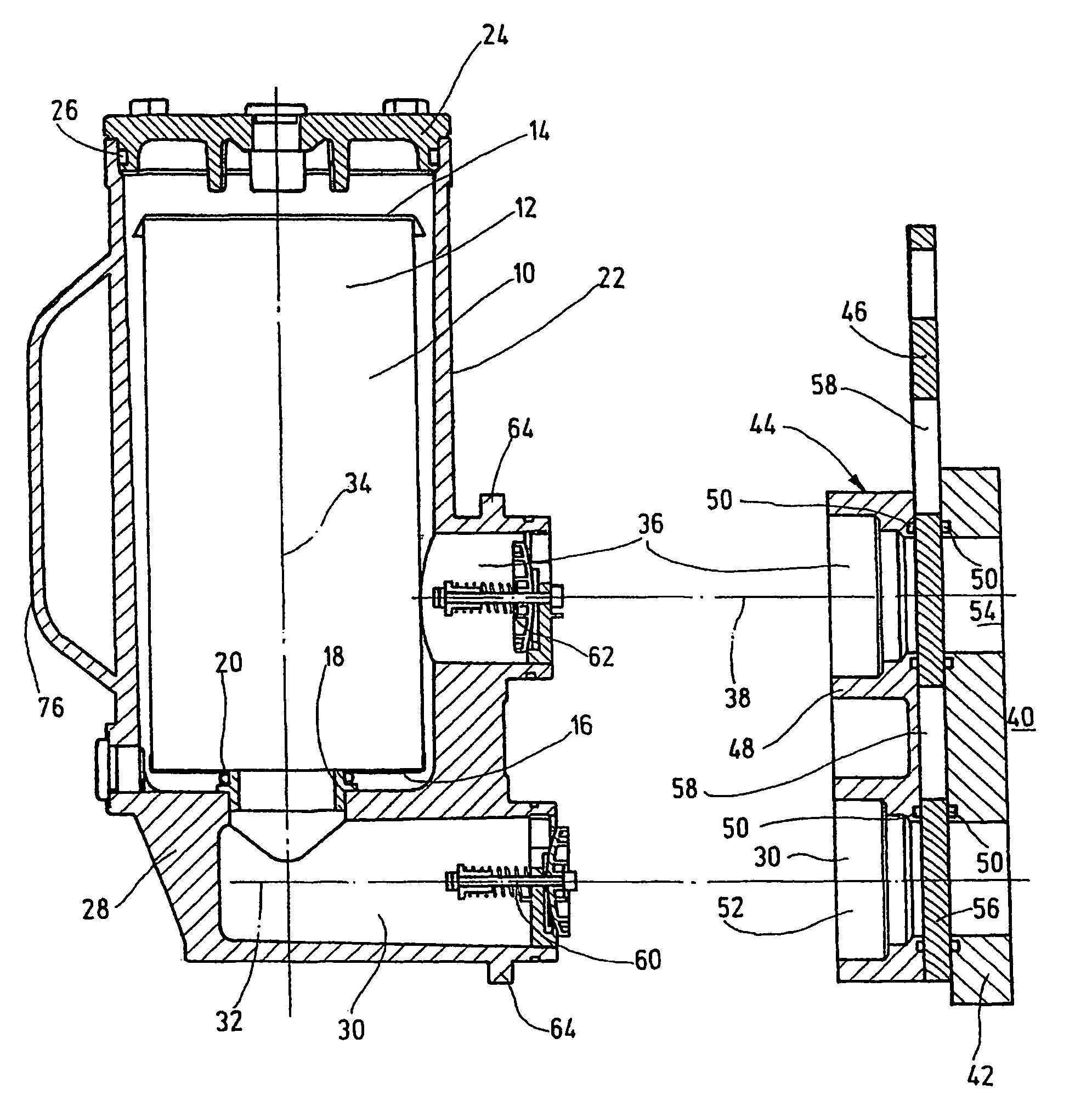
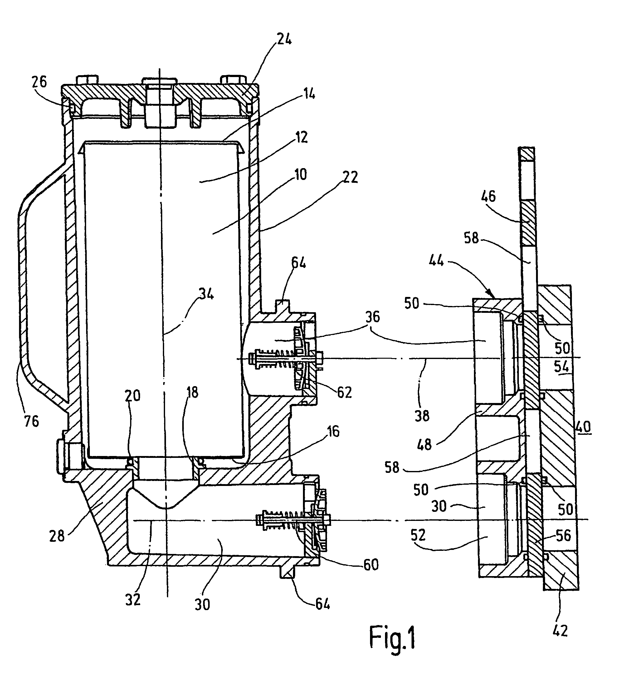
[0012]The filter device shown in the figures has a cylindrical filter element 10 of conventional design. The filter element 10 is used to filter dirt, especially in the form of solid particles, out of a fluid flow, such as a hydraulic medium. For this purpose, the filter element 10 is provided with a preferably pleated filter mat 12 supported on the interior on a perforated support tube (not shown). Furthermore, the filter mat 12 is cylindrical, and held between two end caps 14, 16. This element structure is conventional and prior art, so that it will not be described further. The upper end cap 14 can be equipped with a bypass means, for example a bypass valve (not shown) to ensure that when the filter element 10 is clogged with dirt the fluid flow can freely pass the filter element 10 via the end caps 14, 16 to avoid obstacles in operation of a fluid or hydraulic system. The lower end cap 16, as viewed in FIG. 1, is held along one cylindrical mounting connection piece 18, and is se...


PUM

PropertyMeasurementUnit
areaaaaaaaaaaa
foulingaaaaaaaaaa
displacementaaaaaaaaaa

Abstract

A filter device includes at least one filter element (10) housed in a filter housing (22) and connected for the flow of fluid by fluid connections (30, 36) to a fluid device, in particular in the form of a hydraulic tank (40), using a connector device (44). A plunger valve arrangement is achieved, whereby the connector device (44) is provided with at least one longitudinally-displaceable blocking piece (46). In the blocking position, the blocking piece blocks the provided fluid connections (30, 36). After displacement into an open position, it releases the fluid connections. A blocking or releasing of the fluid connections in a rapid operation process is permitted to carry out a filter element exchange for the used filter medium.

Description

FIELD OF THE INVENTION[0001]The present invention relates to a filter device with at least one filter element held in a filter housing, connected to carry fluid by fluid connections to a fluid means, especially in the form of a hydraulic tank, by a connecting device.BACKGROUND OF THE INVENTION[0002]These filter devices are readily available on the market in a plurality of designs and versions. Among their functions is to filter dirt in fluids, such as hydraulic oil, out of these fluids. Hydraulic oil is fouled during installation and when the respective hydraulic system is started up. In addition to this initial fouling, fouling during operation can occur, for example by penetration of dirt at the hydraulic tank due to inadequate tank ventilation, pipe penetrations, piston rod seals, and the like. To the extent fouling within the fluid stored in the hydraulic tank occurs in hydraulic systems of machines such as earth moving machines, excavators or the like, it can be advantageous to...

Claims


Application Information

Patent Timeline
Patent Type & Authority Patents(United States)
IPC IPC(8): B01D35/157B01D35/00B01D27/10B01D29/11B01D35/153B01D35/30F15B21/04
CPCB01D29/114B01D35/153B01D29/96B01D35/30B01D2201/4023
Inventor KLEIN, VOLKMARSANN, NOBERT
Owner HYDAC FILTERTECHNIK GMBH
Why Eureka
Try Eureka