
Device for adjusting and exchanging beamstops

Active Publication Date: 2020-12-24
BRUKER AXS
View PDF0 Cites 2 Cited by
  • Summary
  • Abstract
  • Description
  • Claims
  • Application Information

AI Technical Summary

Benefits of technology

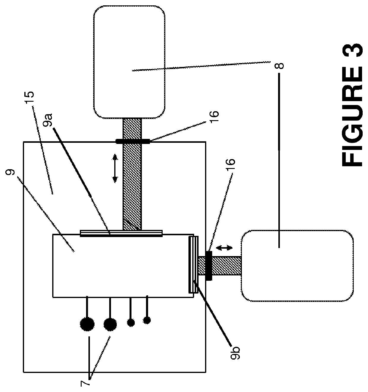
The present invention provides a beamstop arrangement with a positioning and exchanging system for multiple beamstops of different sizes. This system can automatically adjust in vacuum and enable the exchange of beamstops of various sizes. The drive motors are located outside the vacuum, which keeps the technical requirements low for the motors and improves cooling, reduces heat introduction, and minimizes thermal effects on positioning.

Problems solved by technology

In this case, however, variable properties of the beam optical units cannot be corrected.
However, this type of the arrangement has the disadvantage that the beamstop can only have a predetermined size.
This beamstop has only limited suitability for the use in the vacuum of a SAXS device.

Method used


Image

  • Device for adjusting and exchanging beamstops
  • Device for adjusting and exchanging beamstops
  • Device for adjusting and exchanging beamstops

Examples


Embodiment Construction

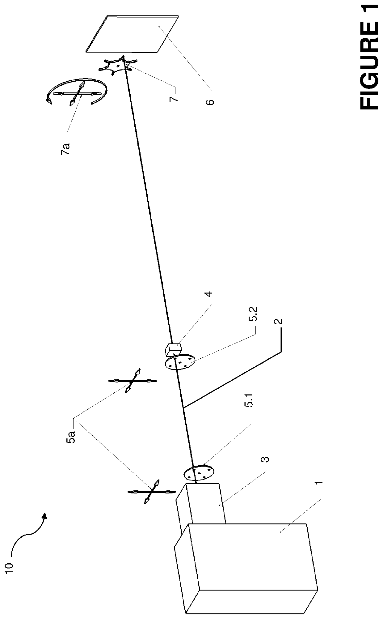
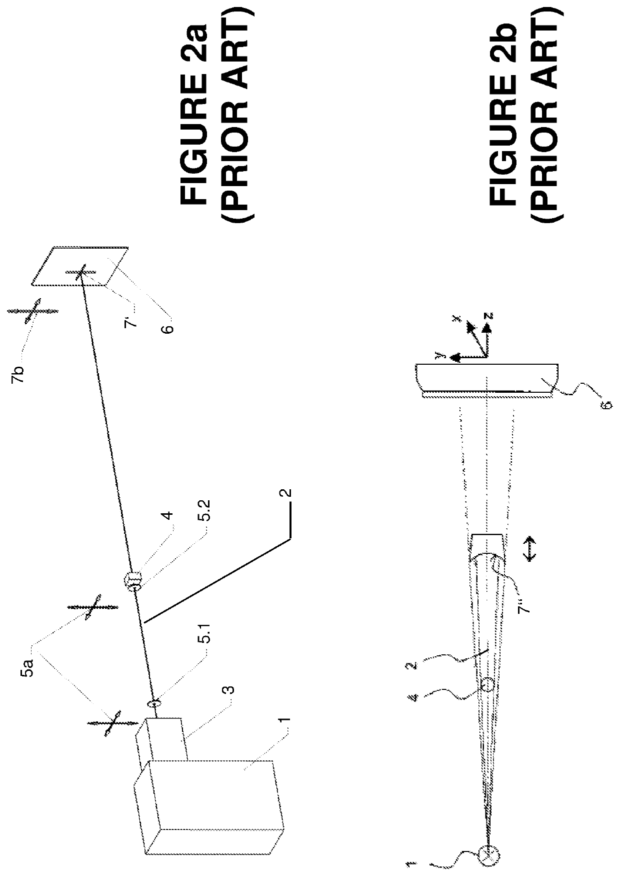
[0064]FIGS. 1 and 3 to 6b each show a schematic view in differing detail of preferred embodiments of the beamstop arrangement according to the invention for an x-ray-optical system 10, while FIGS. 2a and 2b each show a generic x-ray-optical system according to the prior art, with FIG. 2a being representative of the applicant's NANOSTAR system, and FIG. 2b being representative of the system shown in U.S. Pat. No. 7,295,650.

[0065]The x-ray-optical system shown in FIG. 2a comprises an x-ray source 1 having upstream source optical unit 3 for forming the primary x-ray beam 2. This is followed in the beam direction by a first aperture 5.1 and a second aperture 5.2, which are arranged for further beamforming even before the sample 4 to be measured in the primary beam 2, and which have the translational degrees of freedom 5a indicated as arrow crosses shown in the figure.

[0066]After the sample 4, a beamstop 7′ adjustable in an xy plane perpendicular to a z direction is arranged directly bef...


PUM


Abstract

A beamstop arrangement for an x-ray-optical system is adjustable in an xy plane perpendicular to a z-direction for optimizing a ratio of useful radiation reaching a surface to interfering radiation of an x-ray beam in the z-direction. The beamstop arrangement comprises a plurality of beamstops of differing size and / or geometry arranged on an exchanging mount, which is installed on a carriage displaceable in the xy plane by means of a drive unit having at least one positioning motor. The multiple beamstops can be located in a vacuum, while the drive motors and all electronic components can be positioned outside the vacuum, so that no heat development takes place in the measurement region. Corruption of the measurement result due to a changed measurement background is thus avoided.

Description

BACKGROUND OF THE INVENTIONField of the Invention[0001]The present invention relates in general to the field of x-ray-optical systems, especially beamstop arrangements for the primary x-ray beam. A conventional beamstop arrangement of the type in question is known, for example, from U.S. Pat. No. 7,295,650 B2.Description of the Related Art[0002]X-ray-optical methods are used for studying the properties, for example, material properties, of samples. A bundled x-ray or neutron beam is guided for this purpose onto the sample, where it interacts with the sample in manifold ways, in particular by scattering, diffraction, and reflection in the case of grazing incidence. The diffracted x-ray radiation after the interaction process is registered by an x-ray detector and subsequently analyzed to infer properties of the sample.[0003]In many of these methods, only a small part of the primary x-ray radiation from an x-ray source is subject to a diffraction or scattering. By far the largest part...

Claims


Application Information

Patent Timeline
IPC IPC(8): G01N23/201G01N23/207G01N23/20008
CPCG01N23/20008G01N23/201G01N23/2073G01N2223/321G21K1/10G01N23/207
Inventor GEHRLEIN, WOLFGANG
Owner BRUKER AXS
Learn More