
Method and storage medium for replacing process instrument in processing apparatus

a technology for processing apparatus and process instruments, applied in process and machine control, electric programme control, process/developing apparatus completely stopped, etc., can solve problems such as time delay, unsolved problems, and inability to solv

Active Publication Date: 2010-10-19
TOKYO ELECTRON LTD
View PDF9 Cites 12 Cited by
  • Summary
  • Abstract
  • Description
  • Claims
  • Application Information

AI Technical Summary

Benefits of technology

The present invention provides a method for replacing a process instrument in a processing apparatus without interrupting the process in a nearby unit. The method allows for the replacement of a process instrument while a new one is being loaded and a next lot is being processed. This method can be executed using a computer program that causes the computer to confirm the process on the target object is finished in the designated process instrument and provide information that the process instrument replacement operation is permitted to start. The method also allows for the transfer of the target object to another processing unit for further processing while the process instrument replacement operation is being performed. This method ensures a smooth replacement of process instruments without causing any interruptions in the processing process.

Problems solved by technology

However, while the interlock mechanism is in an activated state for maintenance of one of the processing units, the coating / developing apparatus is entirely stopped until the maintenance is finished.
However, depending on the type of a processing unit, unsolved problems remain when an operator simply closes the shutter by a switching operation to set the interlock mechanism disabled.
However, the conventional technique is arranged such that an operator closes the shutter of the transfer port of an objective processing unit by a switching operation, without an automatic judgment as to whether the process in the processing unit is finished.
Accordingly, a time delay tends to be caused after the process in the processing unit is finished and before the shutter is closed and the cover door is opened.
Such a problem may be also caused in replacement or inspection of another process instrument that constitutes a processing unit, such as a nozzle or spin chuck, besides a process cup.

Method used


Image

  • Method and storage medium for replacing process instrument in processing apparatus
  • Method and storage medium for replacing process instrument in processing apparatus
  • Method and storage medium for replacing process instrument in processing apparatus

Examples


specific example

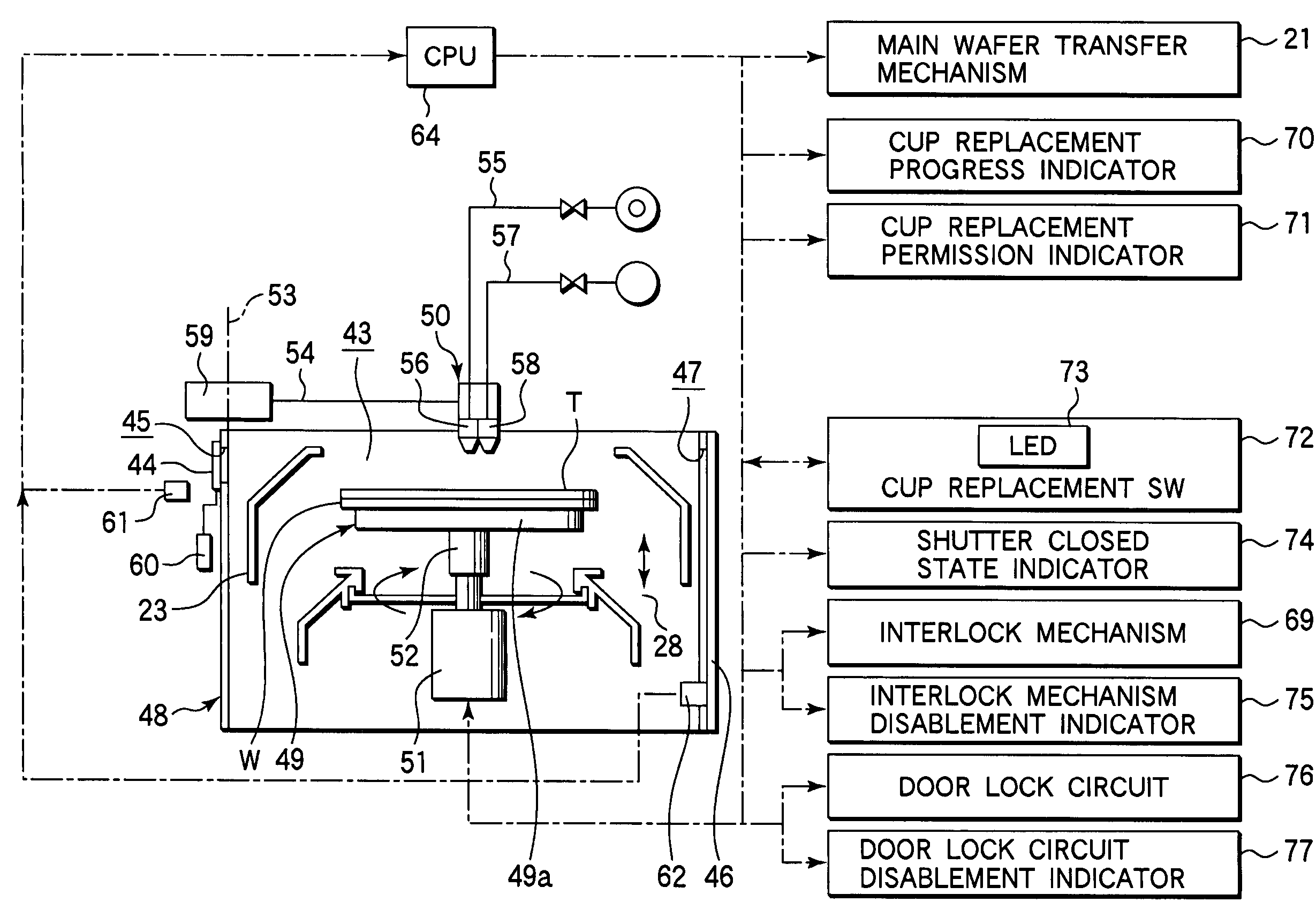
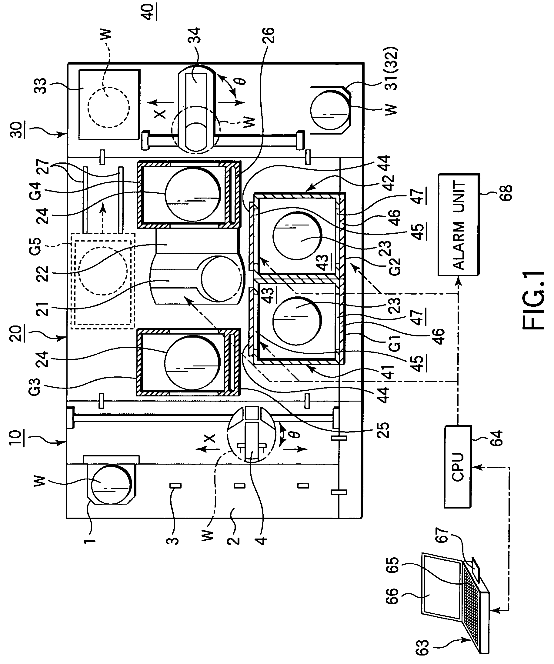
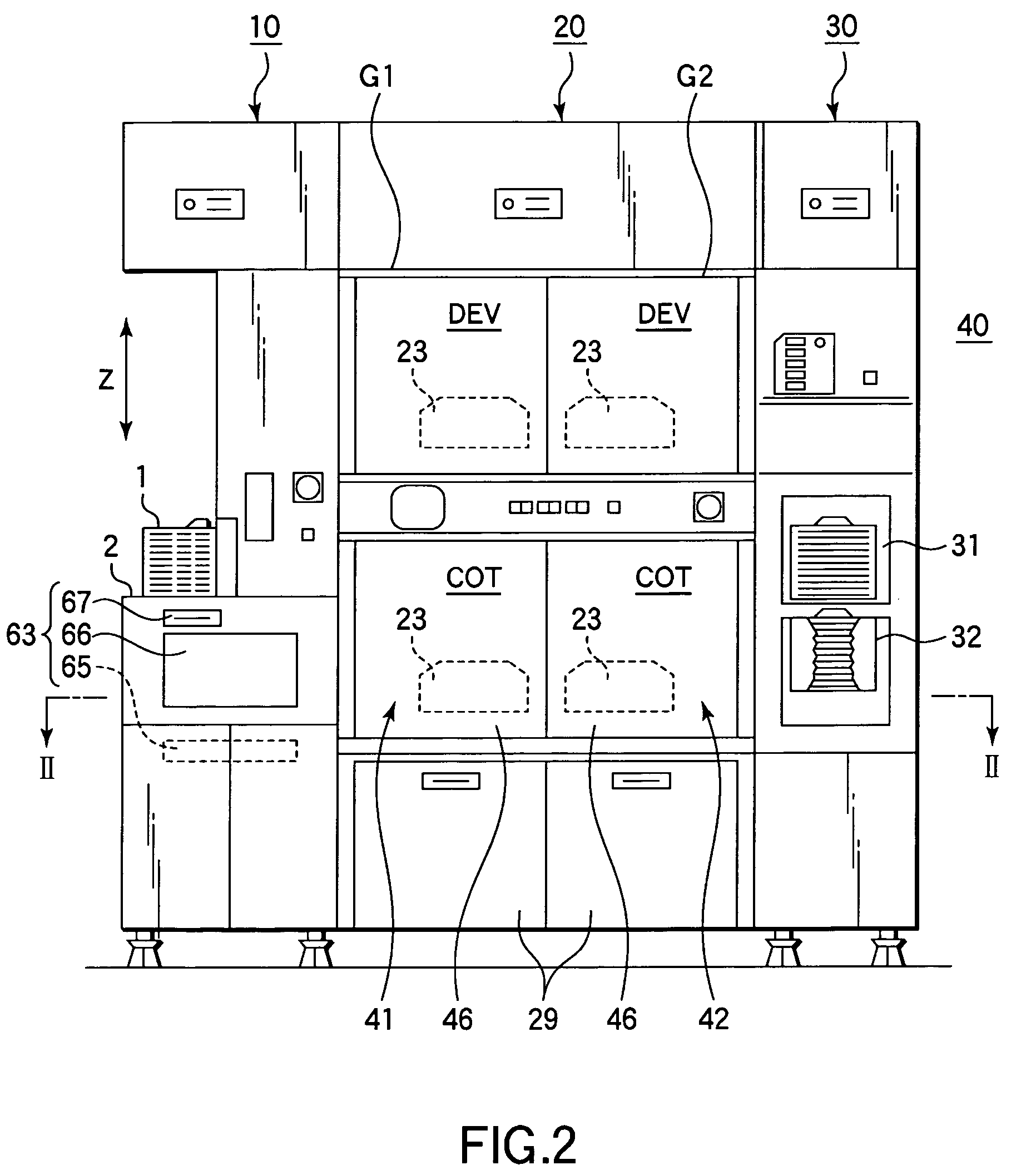
[0092]Next, a detailed explanation will be given of a specific example of a method for replacing a process cup 23 according to the present invention, with reference to FIGS. 4 and 6 to 8.

[0093]At first, a cup replacement appointment is made for a processing unit with a process cup 23 to be replaced (in this case, one of the first coating unit 41 and second coating unit 42) designated by an operator through the I / O section 65 of the control computer 63 with reference to the view of operational image pictures shown on the display section 66. At this time, changes are made in terms of the takeoff suspension of the next lot and the transfer schedule for the next lot.

[0094]As shown in FIG. 6, it is checked by the CPU 64 whether a cup replacement appointment is present (Step S1). Where a cup replacement appointment is present (Yes at Step S1), an alarm for “presence of cup replacement appointment” is indicated by cup replacement progress indicator 70 (see FIG. 4) of the alarm unit 68 or t...


PUM

PropertyMeasurementUnit
temperatureaaaaaaaaaa

Abstract

Disclosed is a method for replacing a process instrument in a processing apparatus, in which a target object is loaded by a transfer mechanism into a processing unit and is subjected to a process by use of the process instrument. The method includes confirming that a process on the target object is finished in a processing unit designated as a process instrument replacement target, and providing information that a process instrument replacing operation is permitted to start. The method further includes, when a shutter of the processing unit designated as the process instrument replacement target is closed to perform a process instrument replacing operation and an operation prohibition state is thereby applied to the transfer mechanism, canceling the operation prohibition state to allow the transfer mechanism to perform a load / unload operation relative to a processing unit not designated as a process instrument replacement target.

Description

BACKGROUND OF THE INVENTION[0001]1. Field of the Invention[0002]The present invention relates to a method for replacing a process instrument in a processing apparatus used for processing a target object, such as a semiconductor wafer, and a storage medium that stores a program for replacement.[0003]2. Description of the Related Art[0004]In general, in the steps for manufacturing semiconductor devices or the like, a photolithography technique is utilized to form a resist pattern on the surface of a substrate to be processed (which will be referred to as a target object), such as a semiconductor wafer or LCD substrate. This photolithography technique includes a resist coating process for applying a resist liquid onto the surface of the target object; a light exposure process for subjecting the resist film thus formed to light exposure with a circuit pattern; and a developing process for supplying a developing solution onto the target object treated by the light exposure process. These...

Claims


Application Information

Patent Timeline
Patent Type & Authority Patents(United States)
IPC IPC(8): B23Q3/155H01L21/677
CPCH01L21/67276Y10S414/135Y10T483/14Y10T483/11Y10T483/10Y10T483/12Y10T483/115Y10T29/4973G05B19/41815G05B19/4189H01L21/67742G05B2219/45031
Inventor TAJIRI, NAOYUKISUZUKI, AKIFUMIHONMA, DAISUKE
Owner TOKYO ELECTRON LTD
Learn More