
Gas insulated switchgear

a switchgear and gas insulation technology, applied in the direction of air-break switch, high-tension/heavy-dress switch, electrical apparatus, etc., can solve the problems of detracting from the quality of gas-insulated switchgear, the electric insulation performance of the solid insulation may become severely impaired,

Active Publication Date: 2010-10-19
KK TOSHIBA
View PDF15 Cites 41 Cited by
  • Summary
  • Abstract
  • Description
  • Claims
  • Application Information

AI Technical Summary

Benefits of technology

[0019]Thus, using CO2 gas, a perflurocarbon, a hydrofluorocarbon, CF3I or the like as electrical insulation media and arc extinguishing media in a gas insulated switchgear allows providing a gas insulated switchgear having good performance overall while reducing global warming impact vis-à-vis conventional SF6 gas used in a gas insulated switchgear.
[0024]An object of the present invention is to provide a gas insulated switchgear having excellent performance and quality, and little global warming impact, by restraining carbon generation as a result of current interruption, also when using as an arc extinguishing medium of the gas insulated switchgear a gas comprising the element C and having a global warming potential lower than that of SF6 gas, for instance CO2 gas, a perflurocarbon, a hydrofluorocarbon, CF3I or the like.
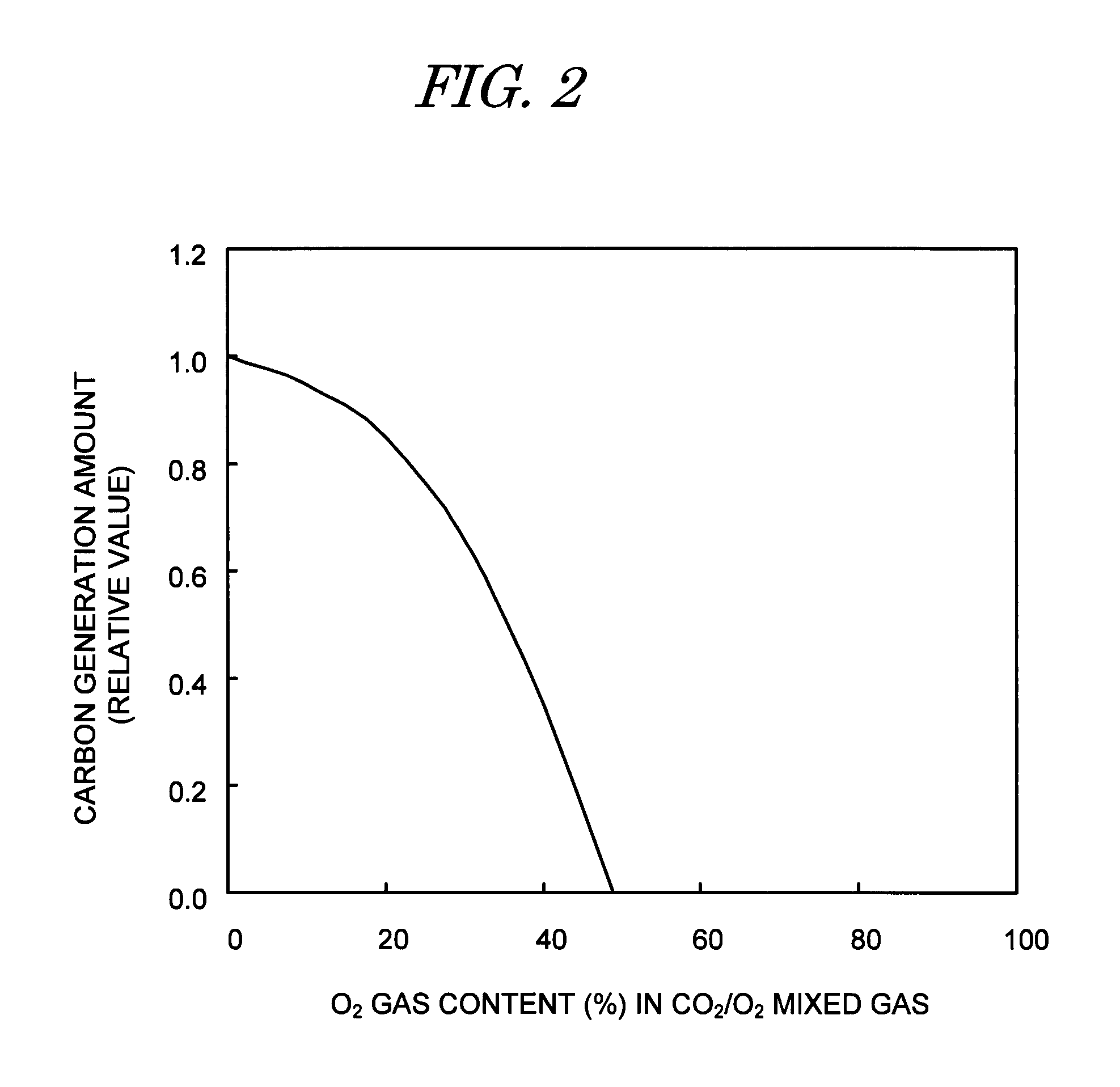
[0027]In the gas insulated switchgear according to the present invention having the above constitution, the main constituent of the insulating gas, as the arc extinguishing medium, is the mixed gas having a gas comprising the element C and other gases. The presence of the element O in the mixed gas allows restraining the amount of carbon generated as a result of current interruption.

Problems solved by technology

However, all these gases comprise the element C, and hence the gases by themselves, or as main constituents of mixed gases, are problematic in that, when used in the gas insulated switchgear, they dissociate, recombine and generate free carbon as a result of the high-temperature arc generated during current interruption.
When the carbon generated as a result of current interruption adheres onto the surface of a solid insulator such as an insulating spacer or the like, the electrical insulation performance of the solid insulator may become severely impaired, thereby detracting from the quality of the gas insulated switchgear.

Method used


Image

  • Gas insulated switchgear
  • Gas insulated switchgear
  • Gas insulated switchgear

Examples


first embodiment

(1) First Embodiment

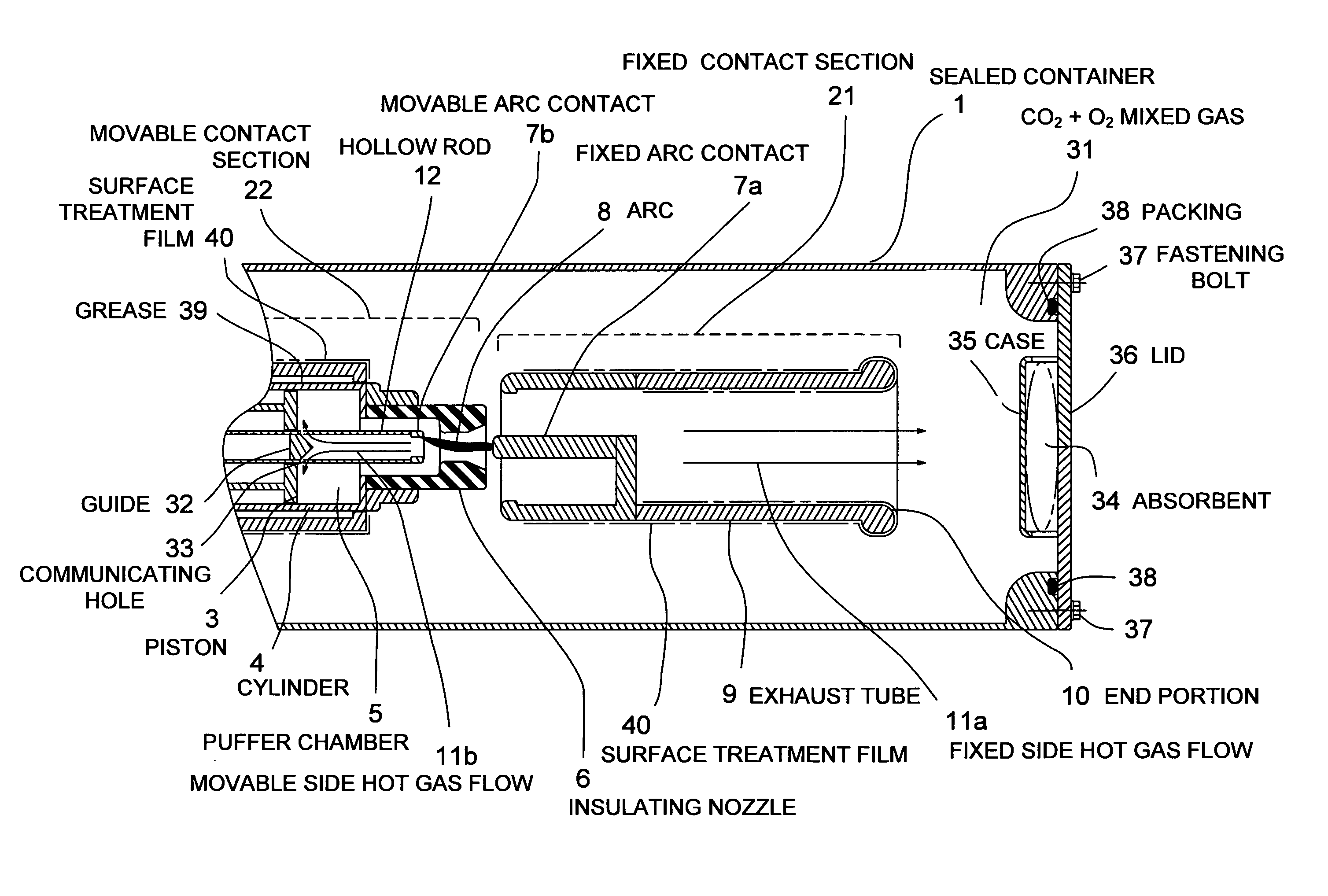
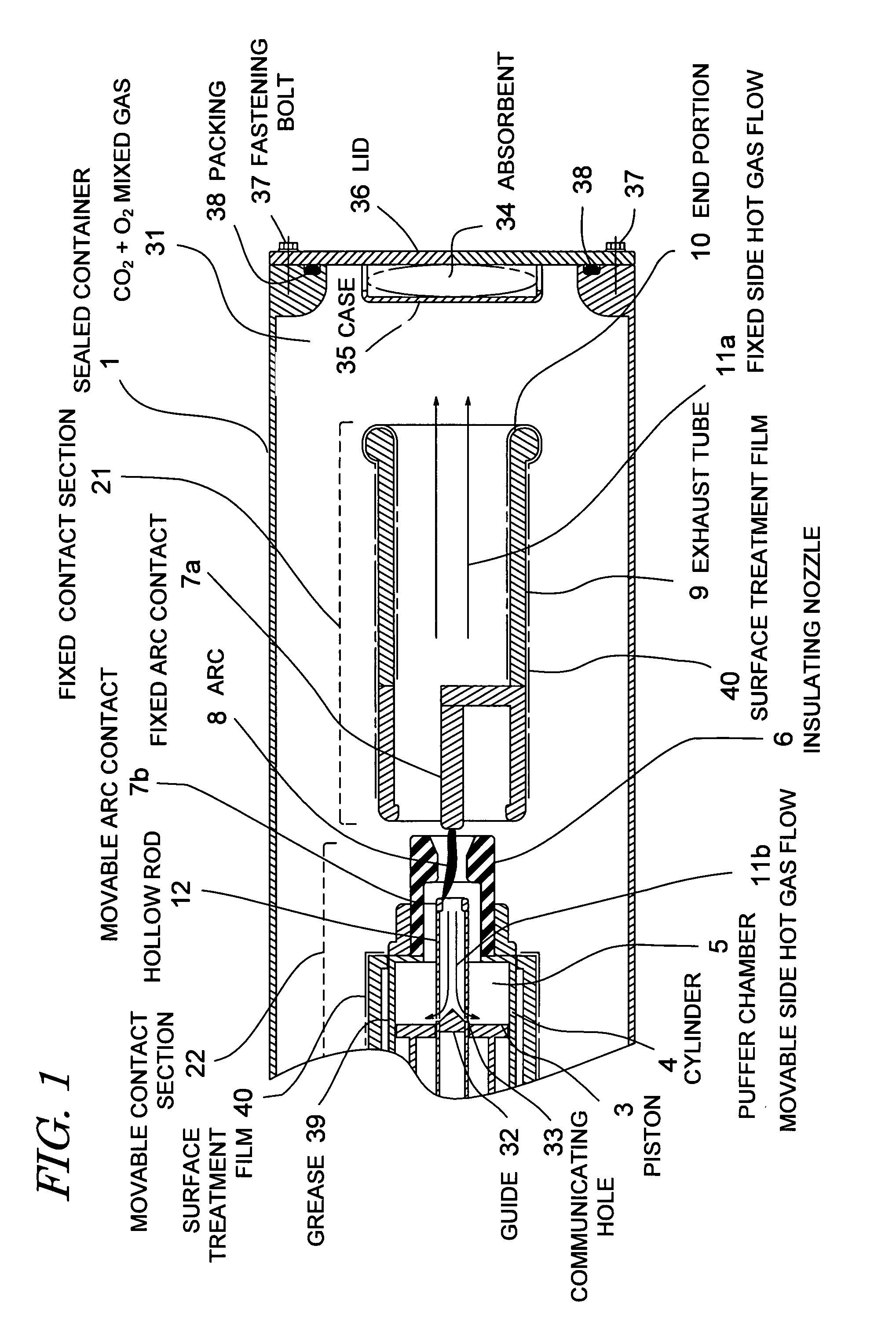
[0037]A first embodiment in accordance with the invention used in a puffer-type gas blast circuit breaker is explained in detail with reference to FIG. 1. In the figure, elements identical to those of the conventional puffer-type gas blast circuit breaker illustrated in FIG. 9 are denoted with the same reference numerals, and their explanation is omitted.

(1-1) Constitution of the First Embodiment

[0038]The basic constitution of a gas insulated switchgear in the present embodiment is identical to that of conventional technology illustrated in FIG. 9. That is, a pair of contacts are arranged inside a sealed container 2 filled with an arc extinguishing gas, during current conduction both contacts are kept in contact to enable conduction, while during current interruption the contacts open, an arc discharge occurs in the gas, and current is shut off thereupon by extinguishing the arc.

[0039]Pressure rise in the puffer chamber 5 is effected herein not only through mecha...

second embodiment

(2) Second Embodiment

[0059]FIG. 5 illustrates a second embodiment in accordance with the present invention. The basic constitution is identical to that of the example illustrated in FIG. 1, except that herein the sealed container 1 is provided with means for detecting CO gas or O3 gas. Specifically, a sensor 41 capable of detecting CO gas or O3 gas is provided in the sealed container 1, information from the sensor 41 being read by an analyzer 42. Alternatively, small amounts of the gas in the sealed container 1 may also be drawn into a sampling container 43, the sampled gas being then analyzed for the content of CO gas and O3 gas in a separate analyzer.

[0060]Every time that current is interrupted in the second embodiment having the above constitution, the filling gas comprising the element C, as well as the O2 gas, decompose and recombine through the action of the arc, so that the concentration of CO gas or O3 generated as a result increases. Even when current is not interrupted, an...

third embodiment

(3) Third Embodiment

[0062]The basic constitution of the gas insulated switchgear in the third embodiment is identical to that of the first embodiment. In the third embodiment, however, is used a mixed gas comprising at least 50% of a gas such as CO2 or the like, comprising the elements C and O and having a lower global warming potential than SF6 gas, and no more than 25% of H2 gas.

[0063]Unlike in the first embodiment, moreover, the thermal energy of the arc is not actively used for raising the pressure inside the puffer chamber, the pressure in the puffer chamber being raised herein mainly through mechanical compression by a piston, and hence the temperature of the arc extinguishing gas does not rise excessively. In concrete terms, the benchmark used herein is a temperature not exceeding 3000K. Specifically, also, the base of the hollow rod 12 is not provided with the communicating hole 33 illustrated in FIG. 1, so that the movable side hot gas flow 11b flowing through the hollow ro...


PUM


Abstract

The invention secures superior performance by restraining carbon generation also when using as an arc extinguishing medium a gas comprising the element C and having a global warming potential lower than that of SF6 gas. A fixed contact section and a movable contact section are arranged opposite each other inside a sealed container filled with an insulating gas. A fixed arc contact and a movable arc contact are provided in the fixed contact section and the movable contact section. The insulating gas is a mixed gas of a gas comprising the element C, as the main constituent, and other gases. The presence of O2 gas in the mixed gas has the effect of restraining the amount of carbon generated. Adding H2 to the mixed gas has the effect of enhancing arc extinguishing performance, compensating for the diminished performance derived from not using actively the thermal energy of the arc.

Description

BACKGROUND OF THE INVENTION[0001]1. Field of the Invention[0002]The present invention relates to a gas insulated switchgear wherein mutually detachable contacts are arranged in a sealed container filled with an insulating gas, and more particularly relates to a gas insulated switchgear having excellent interrupting performance while using an insulating gas having a global warming potential lower than that of SF6 gas.[0003]2. Description of the Related Art[0004]Depending on their intended use and required functionality, a gas insulated switchgear having a current interruption function include, for instance, load switches, disconnecting switches, circuit breakers and the like. In many of these devices, a pair of contacts is arranged within an insulating gas such as SF6 gas or the like, so that during conduction electricity is conducted by maintaining the two contacts in a contact state, while during current interruption the contacts open, an arc discharge occurs thereupon in the gas, ...

Claims


Application Information

Patent Timeline
Patent Type & Authority Patents(United States)
IPC IPC(8): H01H33/04
CPCH01H33/56H01H33/562H01H2033/566H01H2033/888H01H33/04H01H33/91
Inventor UCHII, TOSHIYUKI
Owner KK TOSHIBA
Learn More