Nanosecond flash photolysis system

a flash photolysis and nanosecond technology, applied in the field of laser flash photolysis, can solve the problems of reducing increasing the delay of the probe beam incrementally, and limiting the practical time scale in this case to several nanoseconds, so as to reduce the energy requirement of the pump light source and extend the time interval

Active Publication Date: 2010-10-19
GUSEV ALEX
View PDF4 Cites 10 Cited by
  • Summary
  • Abstract
  • Description
  • Claims
  • Application Information

AI Technical Summary

Benefits of technology

[0011]A LFP system and method of laser flash photolysis have been surprisingly developed and are adapted to substantially lower the energy requirement of a pump light source and to extend a time interval for which a chemical change and detection of the change of a sample may be measured. The LFP system includes a probe light source, a pump light source adapted to produce light pulses with microjoule or higher level energy, a delay generator, and a detector.

Problems solved by technology

The delay of the probe beam is incrementally increased over a desired time interval.
The pump beam energy in such experimental setups is often limited to several microjoules.
However, the longest practical time scale in this case is limited to several nanoseconds.
Expansion of the time scale in such experimental conditions is rather complicated and requires introduction of an expensive laser system and a larger amount of space for the equipment, such as 8-10 ft2.

Method used


Image

  • Nanosecond flash photolysis system
  • Nanosecond flash photolysis system

Examples


Embodiment Construction

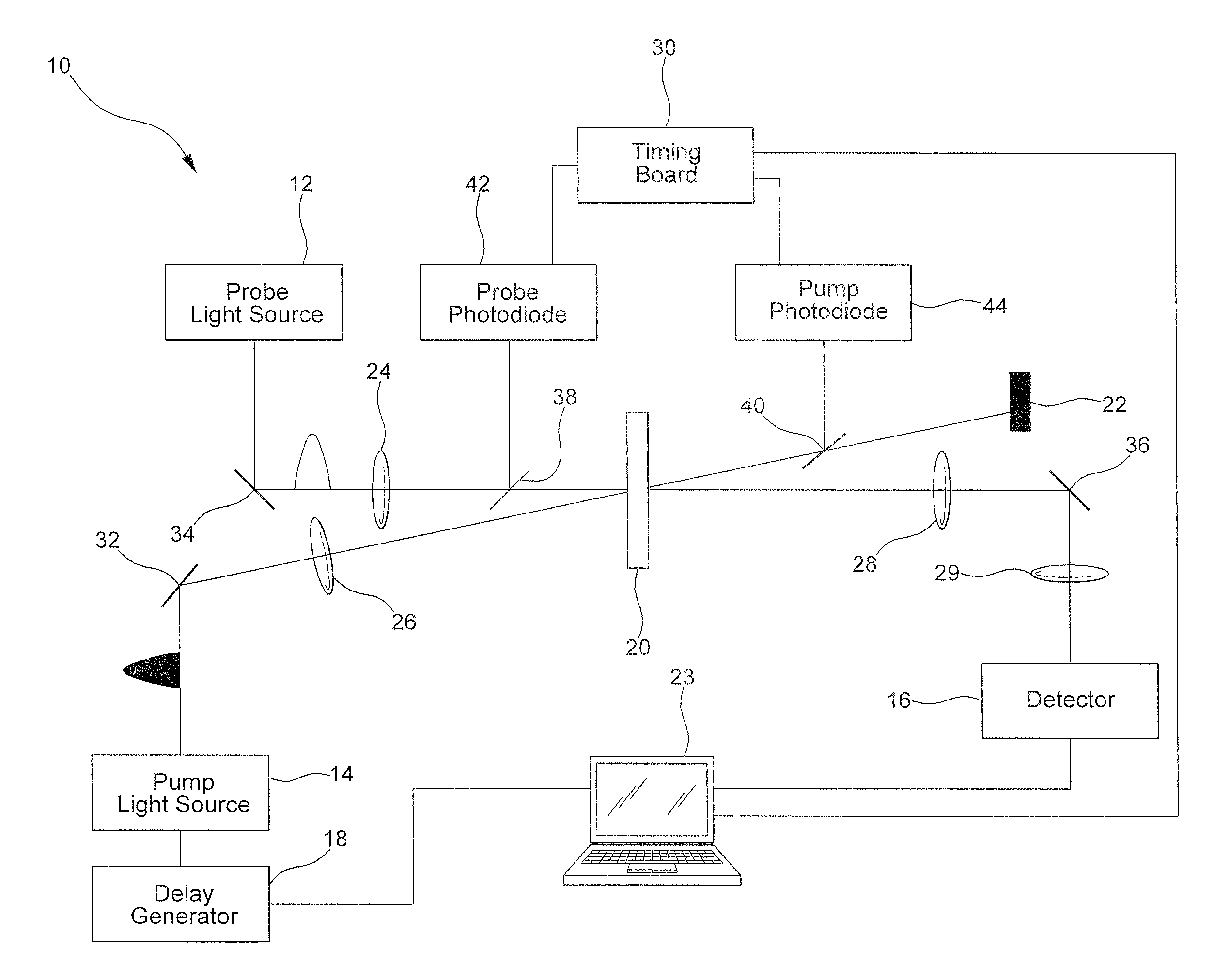
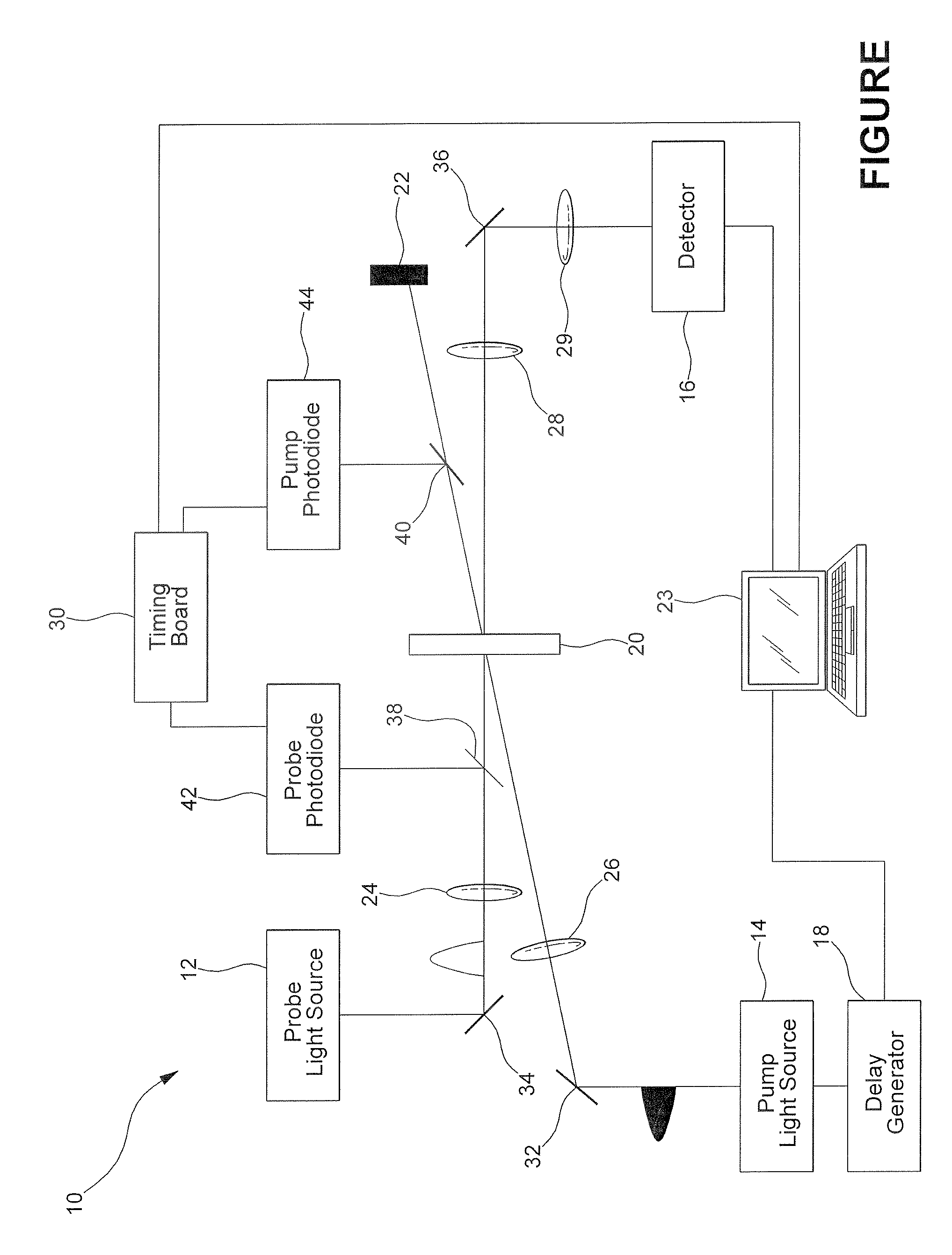
[0015]Referring to the FIGURE, there is illustrated a LFP system 10 which includes a probe light source 12, a pump light source 14, a detector 16, and a delay generator 18.

[0016]The probe light source 12 shown is a photonic crystal fiber pumped by an appropriate laser. The probe light source 12 is adapted to be focused to areas as small as several square microns. It is understood that the probe light source 12 may be any conventional probe light source that is adapted to be focused to areas as small as several square microns such as a Q-switched sub-nanosecond microchip pulsed laser coupled to a photonic fiber, for example.

[0017]The pump light source 14 is typically a laser adapted to produce a collimated beam with an energy level of at least several microjoules and referred to as an excitation light source. The pump light source 14 may be an amplified femtosecond laser, a picosecond laser, a Q-switched nanosecond laser, a dye laser, a nitrogen laser, or a nanosecond microchip laser...


PUM


Abstract

A nanosecond pump-probe LFP system is disclosed and adapted to a substantially lower energy requirement of a pump light source and to electronically extend a time interval during which a chemical change of a sample may be measured. The LFP system includes a photonic crystal fiber based probe light source, a pump light source adapted to produce light pulses with microjoule or higher energy, a delay generator, computer, and a detector.

Description

CROSS-REFERENCE TO RELATED APPLICATION[0001]This application claims the benefit of U.S. provisional patent application Ser. No. 60 / 888,142 filed Feb. 5, 2007.BACKGROUND OF THE INVENTION[0002]1. Field of the Invention[0003]The present invention relates to the field of laser flash photolysis and more particularly to a flash photolysis system with improved performance over existing flash photolysis spectrometers.[0004]2. Description of the Prior Art[0005]Laser flash photolysis (LFP) is a technique utilized to study reaction mechanisms in chemical and biological processes. The technique was introduced in 1966 by Lindqvist at the CNRS in France and the technique was quickly developed by various research groups around the world. LFP was brought about by the invention of the laser, in the early 1960s. The technique of LFP consists of a pulsed laser source that generates a chemical species in a sample to be studied, an optical and electronic system capable of sensing optical changes in a sa...

Claims


Application Information

Patent Timeline
Patent Type & Authority Patents(United States)
IPC IPC(8): G01J3/30
CPCG01N21/636G01N21/631
Inventor GUSEV, ALEX
Owner GUSEV ALEX
Why Eureka
Try Eureka