Process and device for determining the position and the orientation of an image reception means

a technology of image reception and processing device, which is applied in image enhancement, programme control, exposure control, etc., can solve the problems of not reaching high accuracies, affecting the and limiting the optical quality of the camera, so as to achieve high accuracy of the determination of the pose without excessively high costs

Inactive Publication Date: 2010-10-19
KUKA LAB GMBH
View PDF43 Cites 52 Cited by
  • Summary
  • Abstract
  • Description
  • Claims
  • Application Information

AI Technical Summary

Benefits of technology

[0009]The basic object of the present invention is therefore to provide a process and a device for determining the pose (position and orientation) of an image reception means, which can be embodied without excessively high costs while offering high accuracy of the determination of the pose.
[0011]The present invention makes it possible to determine the pose of the camera in real time i.e., at least with the videoactive rate, which makes possible the simple and inexpensive visualization of information associated with any particular pose of the camera, especially internal information of the automatic handling device.
[0020]Provisions are made according to a preferred embodiment of the present invention for the pose of an automatic handling device relative to another one to be determined by means of a mark arranged on an automatic handling device and a measuring means, such as a camera or a sensor, which is arranged at the other automatic handling device. The camera and the robot carrying same with the robot's internal measuring means as well as AR system components form one unit according to the present invention. A second robot can be considered to be part of a working cell, whose real conditions are to be augmented with information from that working cell, e.g., the path programmed at the second robot. It is necessary for this that the first robot knows where it is located in relation to the second robot. This relationship can be established by calibration. After the calibration, it is easy for the robot control of the first robot to transform the data from the robot control of the second robot into the image coordinates of its camera and to augment the transformed data into the image recorded.
[0025]If the guiding of the camera is taken over by a second robot, which looks toward the first robot or the working space processed by the first robot, this is a special form of the present invention, in which a robot actively moves a camera in order to make it possible to insert virtual objects into the camera image in the correct position. The peculiar feature of this is that the two robots are related to the same system of coordinates and can easily exchange information that is essential for visualization via their respective controls. This facilitates the insertion of the desired internal information of the robot. The robots are calibrated with one another for this purpose. The robots can also be guided / moved in such a way as to avoid collisions when the controls are connected with one another, which is not possible with conventional, purely mechanically operating AR tracking systems. If robot systems with more than six degrees of freedom are used, the redundant degrees of freedom can be used to evade collisions and singularities (which are very easily entered in case of hand-guided robots) and to evade obstacles. The control of the camera-guiding robot could have collision avoidance algorithms, which automatically ensure that the robot will not collide anywhere while being guided manually. This is a great advantage over purely passive systems, because the user must always ensure that the system does not collide.

Problems solved by technology

However, the accuracy that can be achieved in the determination of the pose is limited by the optical quality of the camera, the quality of the calibration of the camera, the accuracy of the determination of the position of the marks and the precise arrangement of the marks at known sites in the world or environment and the quality of the image processing.
Arranging a sufficient number of optical marks in real manufacturing environments and measuring them—manually—before the beginning of a robot programming is very complicated.
On the one hand, such a procedure has not hitherto been embodied in a version fit at least for practical use and, on the other hand, it might not reach high accuracies.
Such a procedure is associated with high costs.
In addition, the range of action of the viewer is greatly limited in case of mechanical sensor systems, such as cross-wire systems.
There must be a direct visual contact between the transmitter and the receiver in case of optical or acoustic systems, which is usually hardly guaranteed in real manufacturing environments.
Moreover, time-consuming calibration of the additional sensor systems is necessary, but hardly practicable, before the beginning of the programming.

Method used


Image

  • Process and device for determining the position and the orientation of an image reception means
  • Process and device for determining the position and the orientation of an image reception means
  • Process and device for determining the position and the orientation of an image reception means

Examples


Embodiment Construction

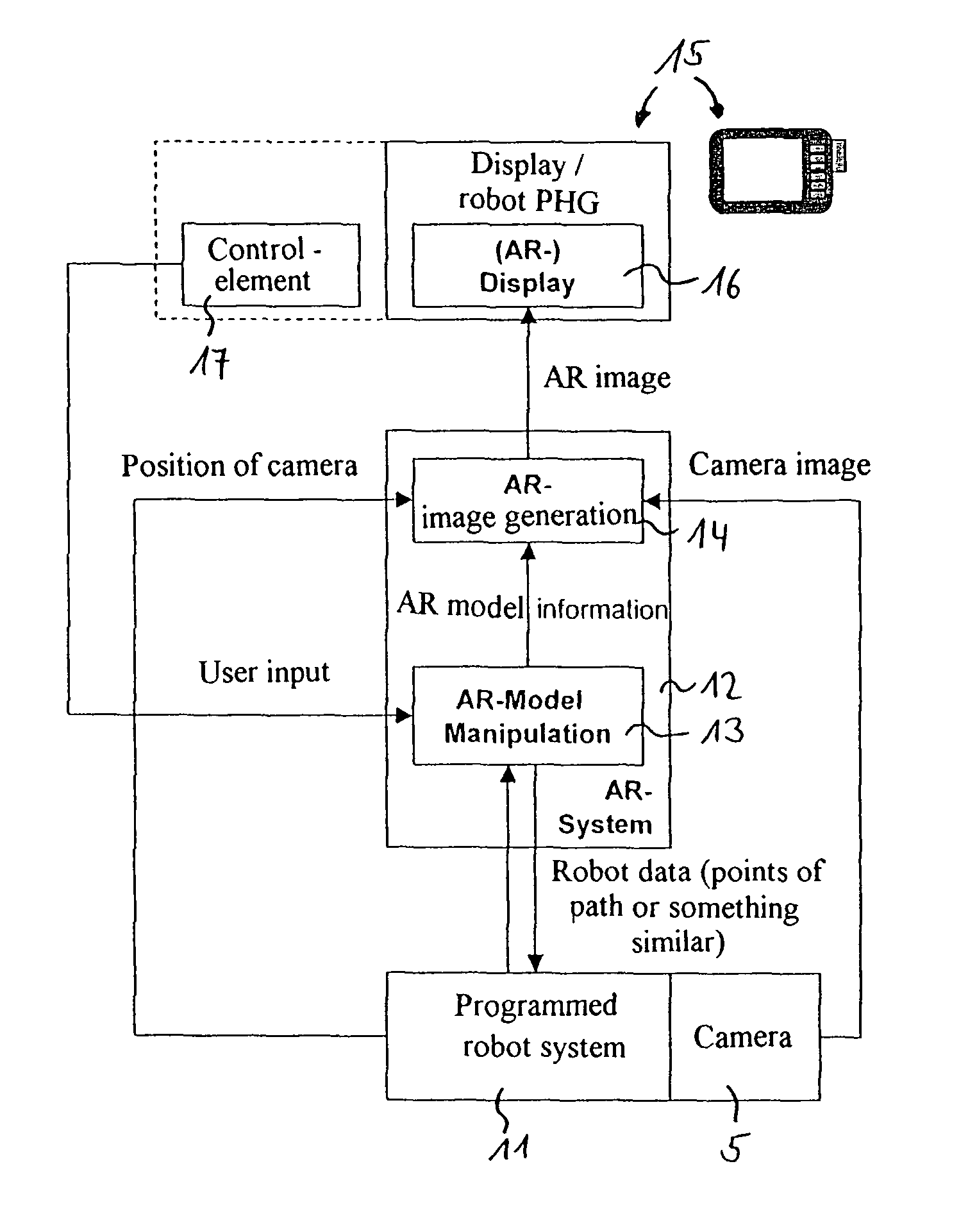
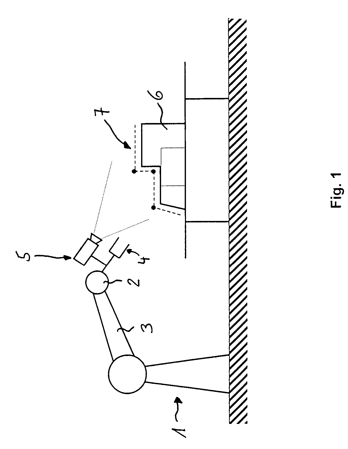
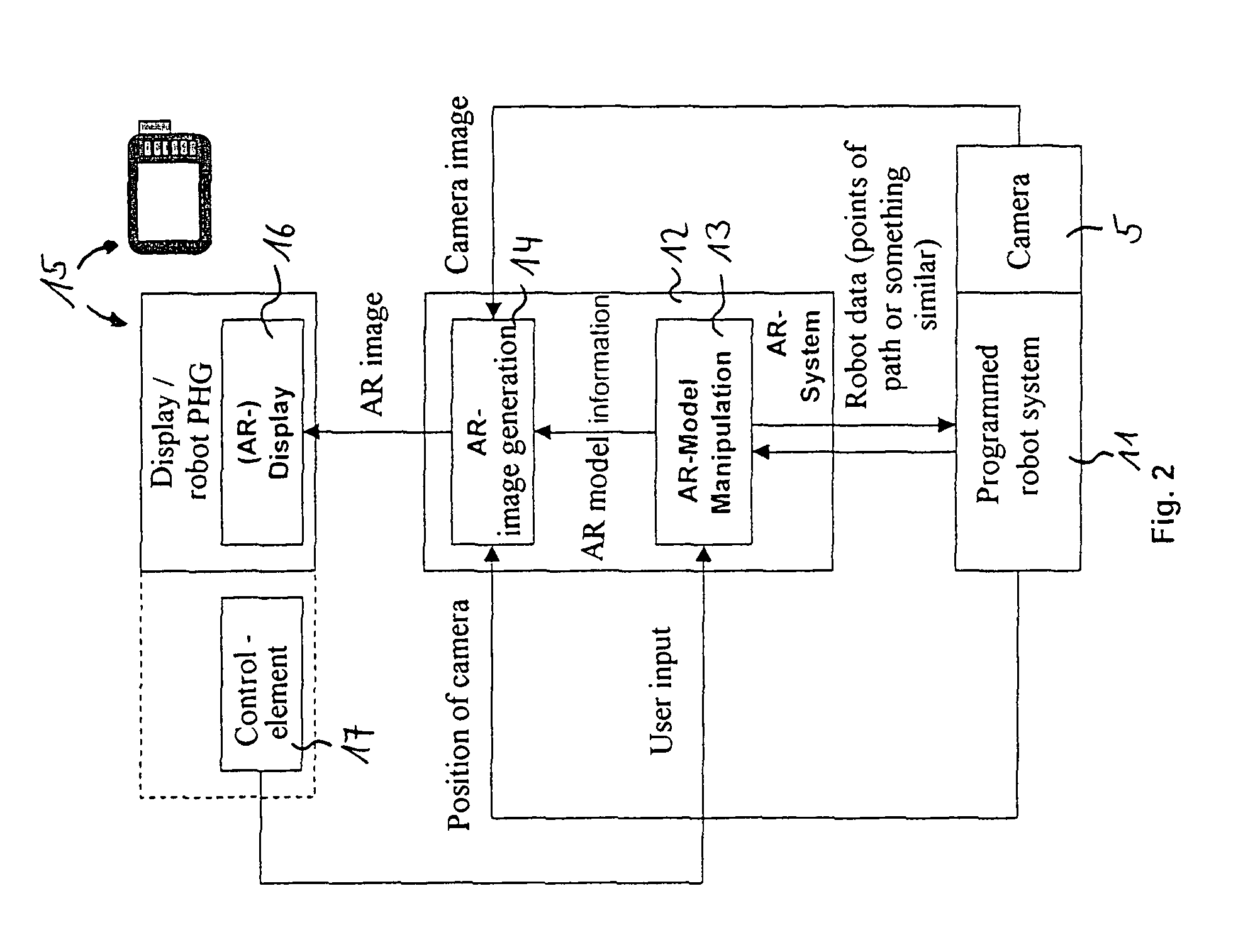
[0039]Referring to the drawings in particular, FIG. 1 schematically shows, as an example of an automatic handling device or robot, a multiaxial industrial robot 1, which is provided with a tool 4 in its hand area 2 at the front end of its robot arm 3. An image reception means 5 in the form of a camera is arranged at the tool 4 in the exemplary embodiment being shown. Furthermore, workpieces 6 as well as a programmed robot path 7, which is to be traveled by the robot and is associated with the workpieces 6, are shown.

[0040]Not shown is a display associated with an operator or user with a display of the real image recorded by the image reception means 5 and with the insertion of virtual information, especially image information, assigned to the real image in the correct position.

[0041]To display augmented objects by insertion in the correct position on the display, the position of the image reception means 5 (camera) in the space must be known. This can be determined with high precisi...


PUM


Abstract

A process and a device are provided for determining the pose as the entirety of the position and the orientation of an image reception device. The process is characterized in that the pose of the image reception device is determined with the use of at least one measuring device that is part of a robot. The device is characterized by a robot with an integrated measuring device that is part of the robot for determining the pose of the image reception device.

Description

CROSS REFERENCE TO RELATED APPLICATIONS[0001]This application claims the benefit of priority under 35 U.S.C. §119 of DE 103 45 743.7 filed Oct. 1, 2003, the entire contents of which are incorporated herein by reference.FIELD OF THE INVENTION[0002]The present invention pertains to a process and a device for determining the pose as the entirety of the position and orientation of an image reception means.[0003]The present invention pertains, in particular, to a process and a device for determining the position and the orientation of an image reception means, which receives images of the real environment, into which virtual information, such as computer-generated or even separately recorded and stored information, is also inserted, as this happens in case of so-called “augmented reality” or AR. In automatic handling devices and robots, which are preferably those according to the standard EN ISO 8373 within the framework of the present invention, the position and the orientation are summ...

Claims


Application Information

Patent Timeline
Patent Type & Authority Patents(United States)
IPC IPC(8): G05B15/00G05B19/00G01B11/00B25J9/16G01B11/03G01B11/26G06T7/00
CPCB25J9/1697G06T7/0042G05B2219/36167G05B2219/39045G05B2219/39046G05B2219/39057G05B2219/39114G05B2219/39449G05B2219/39451G06T2207/30244G06T7/73
Inventor KAZI, ARIFBISCHOFF, RAINER
Owner KUKA LAB GMBH
Why Eureka
Try Eureka