Method and apparatus for dispensing liquid in a beverage brewing machine

a beverage brewing machine and liquid dispensing technology, which is applied in the direction of liquid dispensing, liquid/fluent solid measurement, and opening closed containers, etc., can solve the problems of drip brewed coffee, poor quality of product from such beverage brewing machines, and bitter taste, so as to reduce the brewing time and reduce the back pressure

Active Publication Date: 2010-10-26
1693778 ONTARIO LTD
View PDF16 Cites 4 Cited by
  • Summary
  • Abstract
  • Description
  • Claims
  • Application Information

AI Technical Summary

Benefits of technology

[0011]Advantageously, air is pumped into the dispensing chamber and water is pumped out. Thus, the air provides a slight back pressure that increases the flow of water during pumping of the water out of the chamber to an injector in a cartridge. Brewing time is reduced while consistently providing a controlled amount of liquid at a desired pressure to a cartridge during brewing. In one aspect, the liquid pump is a pulsating pump. Thus, liquid is pumped by air assisted pulsating pumping of the liquid to obtain greater volume of liquid flow during pumping.

Problems solved by technology

Referring in particular to coffee, the quality of product from such beverage brewing machines is generally considered poor by comparison to drip brewed coffee.
Unfortunately, selection of higher quality coffee beans only partly addresses this problem as the brewing process itself contributes to the poor quality of coffee produced.
One of the problems is attributed to the brewing time for such brewing machines, which is often greater than 31 seconds and sometimes up in the range of 40 to 45 seconds for delivery of 10 Oz of liquid.
This is a long brew time for the volume of water delivered and the volume of coffee grinds in the cartridge, causing over extraction of the coffee grinds and resulting in a bitter taste.
While brew time is one important factor, other important factors include the water pressure and control of the quantity of water delivered to the cartridge as an incorrect amount of water also negatively affects the coffee produced.

Method used


Image

  • Method and apparatus for dispensing liquid in a beverage brewing machine
  • Method and apparatus for dispensing liquid in a beverage brewing machine
  • Method and apparatus for dispensing liquid in a beverage brewing machine

Examples


Embodiment Construction

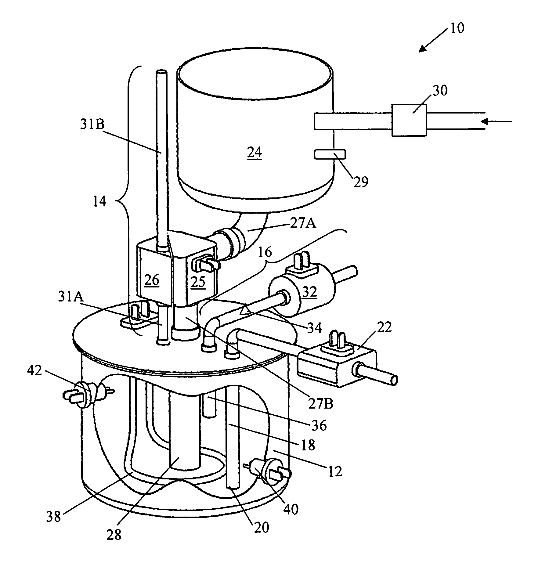
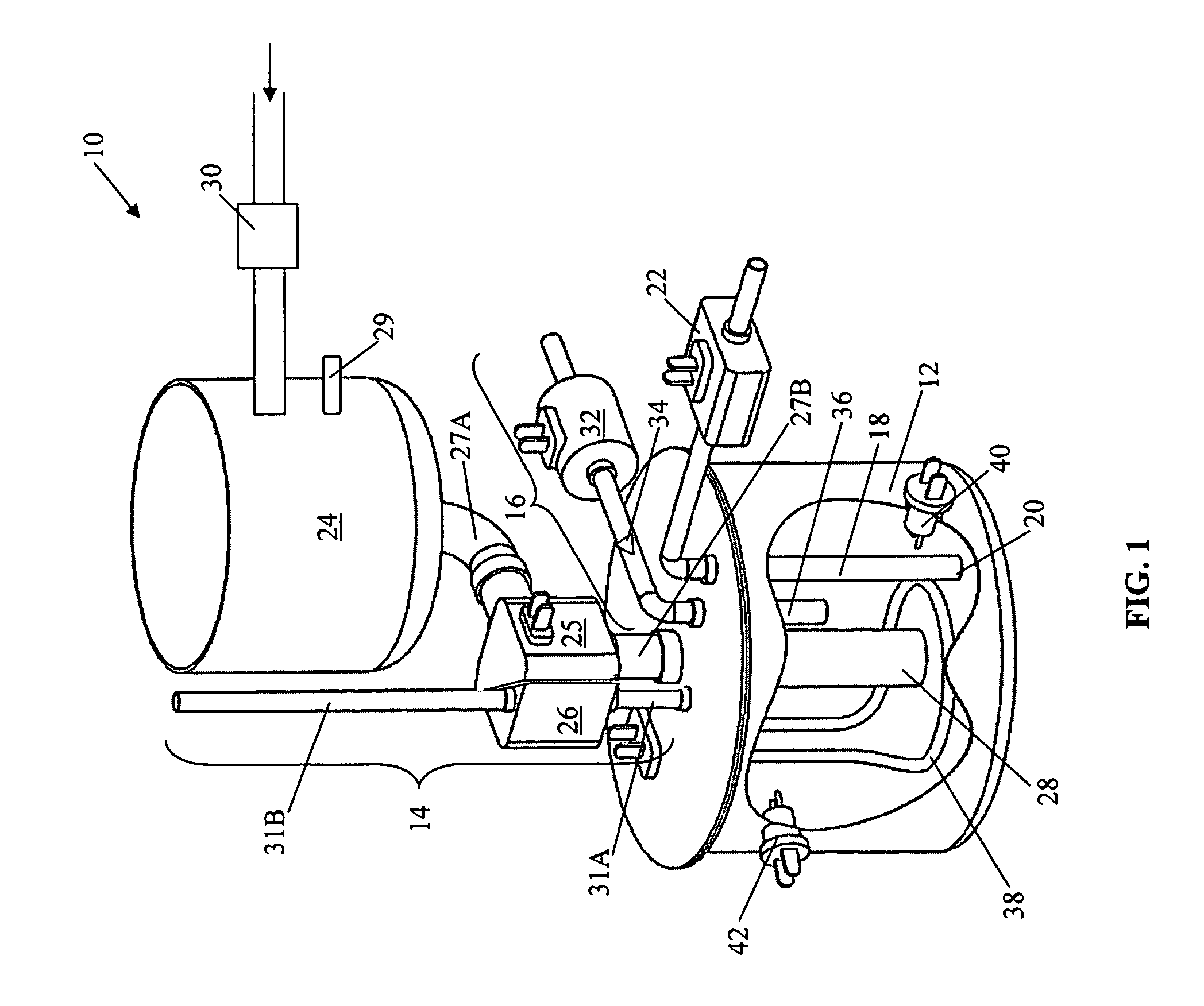
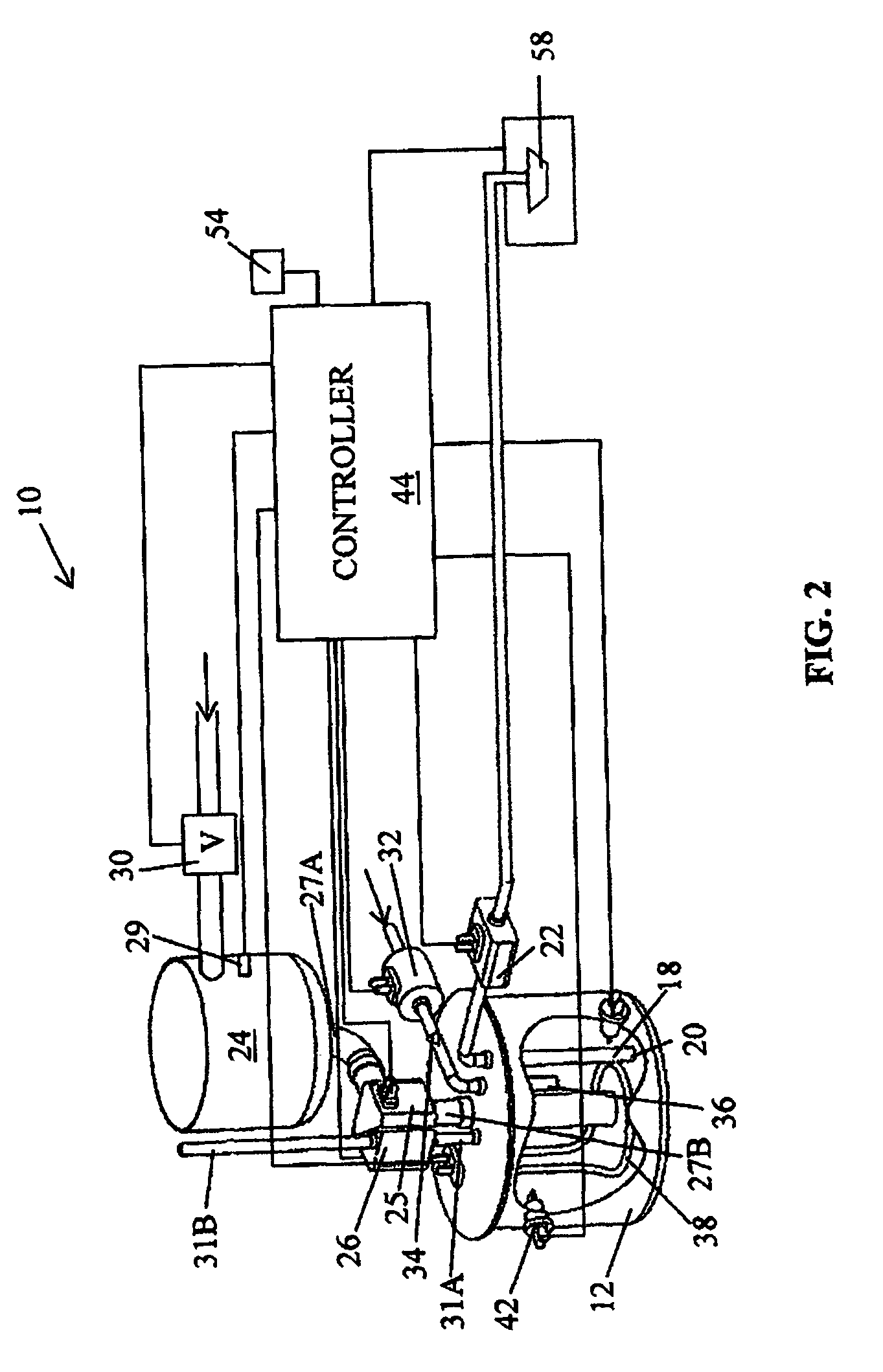
[0018]Referring first to FIG. 1, there is shown a liquid dispensing apparatus for use in a beverage brewing machine, the liquid dispensing apparatus indicated generally by the numeral 10. The liquid dispensing apparatus 10 includes a heating and dispensing chamber 12. A liquid delivery and air venting arrangement 14 is in communication with an interior of the heating and dispensing chamber 12 for delivery of liquid thereto and for venting air therefrom. An air pump assembly 16 is in communication with the interior of the heating and dispensing chamber 12 for pumping air into the heating and dispensing chamber 12. A liquid discharge conduit 18 is in communication with the interior of the heating and dispensing chamber 12 for discharging liquid therefrom and an end 20 of the discharge conduit is located at a predetermined level of the heating and dispensing chamber 12. A liquid pump 22 is connected to the liquid discharge conduit 18 for pumping liquid out of the heating and dispensing...


PUM


Abstract

A liquid dispensing apparatus for use in a beverage brewing machine, the liquid dispensing apparatus, includes a dispensing chamber, a liquid delivery and venting arrangement in communication with an interior of the dispensing chamber for delivery of liquid thereto and for venting air therefrom, an air pump assembly in communication with the interior of the heating and dispensing chamber for pumping air into the dispensing chamber, a liquid discharge conduit in communication with the interior of the heating and dispensing chamber for discharging liquid therefrom, an end of the discharge conduit located at a predetermined level of the dispensing chamber, and a liquid pump connected to the liquid discharge conduit for pumping liquid out of the heating and dispensing chamber. During liquid dispensing, the liquid delivery and venting arrangement is closed.

Description

FIELD OF THE INVENTION[0001]The present invention relates to a liquid dispensing apparatus for delivery of liquid in a beverage brewing machine.BACKGROUND OF THE INVENTION[0002]Single serving beverage dispensing machines are very popular for providing a fresh tasting beverage in a short period of time without having to produce multiple servings. Single serving beverages are produced in beverage dispensing machines using beverage cartridges containing products such as coffee grinds, tea leaves or other soluble products.[0003]When operating a beverage dispensing machine of this sort, a user typically loads a new cartridge into a cartridge holder located in, for example, a slide mechanism and slides the mechanism into place for brewing. Once in place, the beverage making process begins by injection of a hot or cold liquid under pressure into the cartridge, through the beverage product, and out of the cartridge into a cup or mug. While such beverage dispensing machines provide a brewed ...

Claims


Application Information

Patent Timeline
Patent Type & Authority Patents(United States)
IPC IPC(8): A47J31/00
CPCA47J31/32A47J31/36A47J31/40A47J31/46A47J31/469A47J31/407
Inventor HALE, ROBERT
Owner 1693778 ONTARIO LTD
Why Eureka
Try Eureka