In-situ detection and analysis of methane in coal bed methane formations with spectrometers

Inactive Publication Date: 2010-10-26
GAS SENSING TECH CORP
View PDF19 Cites 18 Cited by
  • Summary
  • Abstract
  • Description
  • Claims
  • Application Information

AI Technical Summary

Benefits of technology

[0016]Another object of the invention is to provide a method and measuring system to accurately measure a concentration of methane in a coal bed methane well and calculate a

Problems solved by technology

While industry has developed methods to enhance production from formations that exhibit poor physical characteristics such as permeability and density, currently no practical methods are available to increase the gas content of a coal seam.
The primary issue in identifying such coal seams involves developing a method and apparatus to quickly and accurately analyze coal seams for gas content.
However, collection of the coal sample usually changes its gas content to a significant extent before gas desorption is monitored.
This degradation of sample integrity leads to degradation of the data collected.
That degradation of data creates significant doubt in the results of those common methods.
As well, because these methods hinge on waiting for the methane to desorb from the coal, they require inordinate amounts of time and expense before the data is available.
A coal bed methane well with varying hydrocarbons from coal to methane and, possibly, bacterial material, provides an environment too complex for such a device to differentiate methane and the other substances of interest.
The device is not capable of resolving signals from different hydrocarbons to a useful extent, and the device is not capable o

Method used


Image

  • In-situ detection and analysis of methane in coal bed methane formations with spectrometers
  • In-situ detection and analysis of methane in coal bed methane formations with spectrometers
  • In-situ detection and analysis of methane in coal bed methane formations with spectrometers

Examples


Example

DETAILED DESCRIPTION OF THE DRAWINGS

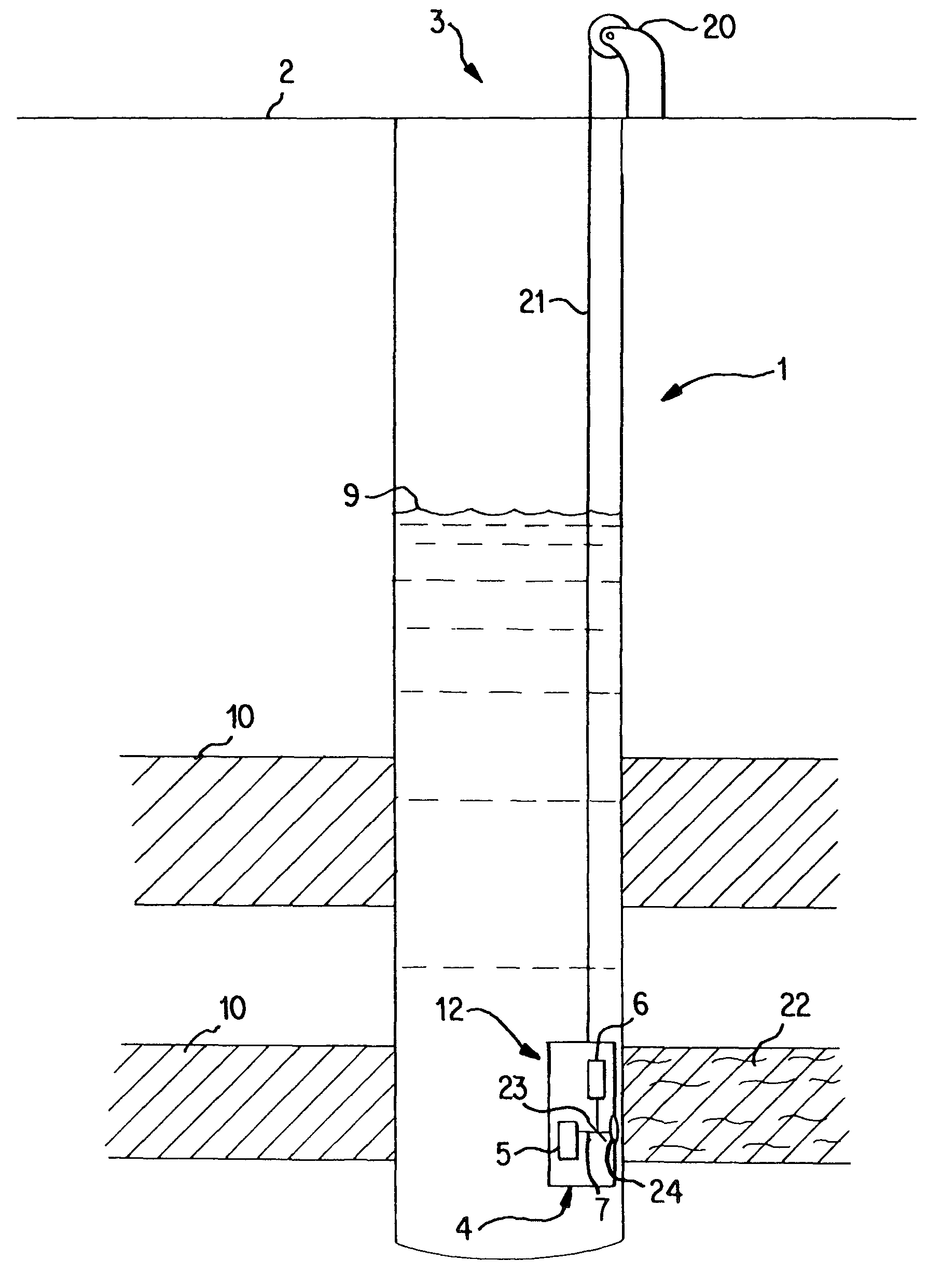
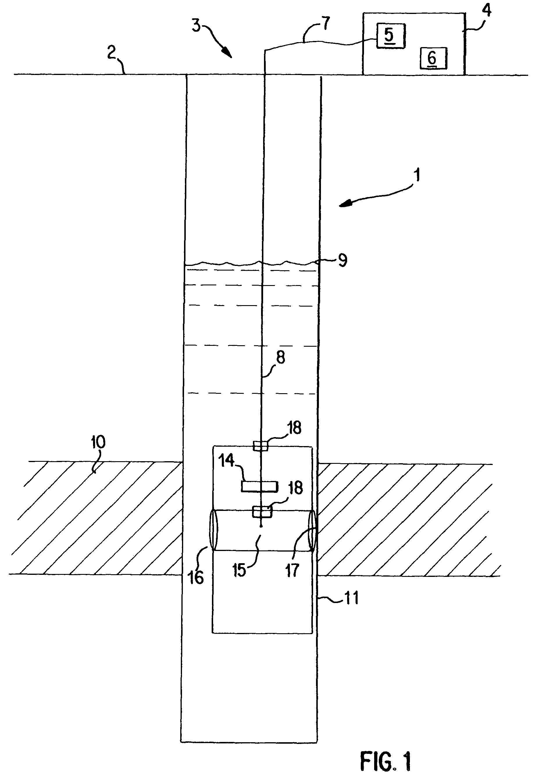
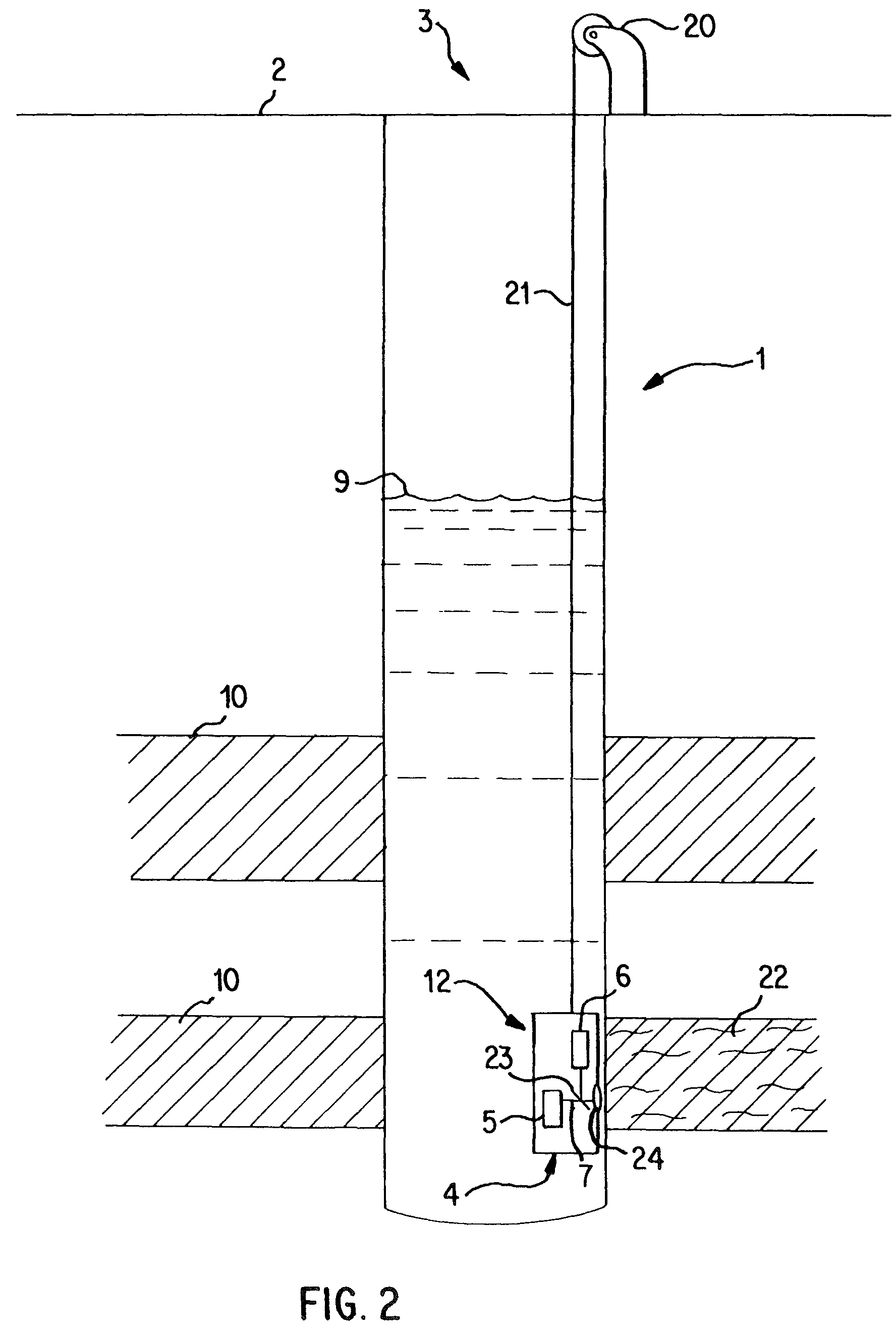
[0037]FIG. 1 shows a coal bed methane well 1 with a borehole 3 extending from a well head to a coal seam 10 with an aquifer fed water level 9. The spectrometer 4 is located at or near the wellhead and includes a radiation source 5 for producing a radiation to transmit down the borehole 3 to a sample interface 25. The radiation from the radiation source is transmitted by way of at least one optical pathway 7. The sample, in this case being water, interacts with the radiation transmitted from the radiation source 5, and a characteristic radiation for the sample is produced by the interaction. The characteristic radiation is then transmitted by an optical pathway 7 to a detector 6 located in the spectrometer 4 at the surface. A suitable optical pathway 7 for transmission is optical fiber 8. Similar elements are represented by the same reference numeral in the drawings.

[0038]The optical fiber 8 extends down the borehole 3 to the housing 12 and feeds i...


PUM


Abstract

A measuring system for in-situ measurements down a well (1) by a spectrometer (4) is provided. The spectrometer (4) includes a radiation source (5) and a detector (6). A probe (15) optically connected to the spectrometer (4) and includes an optical pathway (7) for transmission of a radiation from the radiation source (5) and at least a second optical pathway for transmission of a characteristic radiation from a sample to the detector (6). A positioner is provided to position the probe (15) near a side surface (11) of the borehole (3) and to optically couple the optical pathways (7) to the side surface (11), wherein the probe (15) is traversable up and down the well (1) by way of a guide operatively connected to the probe (15) and to a fixed location at the wellhead. By use of the apparatus and method a concentration of methane or other substance of interest is obtained, and thereby, a potential production of a coal bed methane formation is obtained.

Description

CROSS REFERENCE TO RELATED APPLICATIONS[0001]This application is a continuation of International Patent Application No. PCT / US01 / 11563, filed Apr. 11, 2001, designating the United States of America, and published as WO 01 / 77628, the entire disclosure of which is incorporated herein by reference. Priority is claimed based on Provisional Application Nos. 60 / 196,620, 60 / 196,182, 60 / 196,523 and 60 / 196,000 filed Apr. 11, 2000.TECHNICAL FIELD[0002]This invention relates to in-situ methods of measuring or analyzing dissolved, free, or embedded substances with a spectrometer and an apparatus to carry out the method. In particular this invention relates to a method and apparatus of analyzing substances down a well. More particularly, this invention relates to a method and apparatus to detect, analyze and measure methane or related substances in subsurface coal bed formations using a portable optical spectrometer to thereby predict a potential methane production of the well.BACKGROUND AND SUM...

Claims


Application Information

Patent Timeline
IPC IPC(8): G01J1/04G01N21/00C12N15/12G01J3/28G01N21/31G01N21/35G01N21/65G01N21/85
CPCG01J3/28G01N21/8507G01V8/02G01N21/359G01N21/65G01N2021/3155E21B49/00G01N21/27G01V8/10
Inventor POPE, JOHNHERRIES, JOHN
Owner GAS SENSING TECH CORP
Why Eureka
Try Eureka