Aberration detection device and optical pickup device provided with same

a detection device and pickup technology, applied in the direction of digital signal error detection/correction, instruments, recording signal processing, etc., to achieve the effect of increasing the absolute value of detection sensitivity, reducing the variation of spherical aberration error signals, and high sensitivity

Inactive Publication Date: 2010-10-26
SHARP KK
View PDF15 Cites 1 Cited by
  • Summary
  • Abstract
  • Description
  • Claims
  • Application Information

AI Technical Summary

Benefits of technology

[0031]In the hologram element 210 illustrated in FIG. 15 and used in the first conventional example, the light beams are divided by the arc of the circle having the radius r11 centered about the optical axis OZ (radius r11 that is approximately 70% of the effective radius r10 of the bundle of light beams 208 determined by the aperture of the objective lens 204). This makes it possible to detect a maximum focal point deviation in divided light beams. Therefore, it is possible to detect the SAES with high sensitivity. However, when the center of the hologram element 210 and the center of the bundle of light beams are displaced in the radial direction by shifting of the objective lens at the time of tracking control, sensitivity of the SAES is greatly changed and detection sensitivity of the SAES decreases.
[0032]On the other hand, in the hologram element 220 illustrated in FIG. 16 and used in the second conventional example, the light beams are divided by the line D22 in the radial direction. This causes no variation in detection sensitivity of the SAES even when the center of light beam dividing means and the center of the bundle of light beams are displaced in the radial direction by shifting of the objective lens at the time of tracking control. However, an absolute value of detection sensitivity of the SAES becomes low (signal quality of the SAES becomes poor) since the division manner in FIG. 16 is greatly different from the division manner that maximizes an absolute value of detection sensitivity of the SAES (division by the arc having the radius r11 that is approximately 70% of the effective radius r10 of the bundle of light beams 208 determined by the aperture of the objective lens 204; see FIG. 15).
[0039]Thus, in the second border extending in the radial direction, the top of the bulge bulging toward the periphery is substantially parallel to the radial direction (direction in which the first border extends), and portions other than the bulge (at least both ends) extend substantially parallel to the radial direction. In this manner, the second border has lines extending in the radial direction at the top of the bulge and the portions other than the bulge. Therefore, even when the condensing optical system is shifted in the radial direction by tracking control for the reason that there is no match between the center of the light beam dividing means and the center of the bundle of light beams, it is possible to prevent light beams from being condensed onto divided regions of the light beam dividing means which are different from divided regions onto which the light beams are supposed to be condensed.
[0040]This prevents light beams divided by the divided regions from being received by light receiving sections of the light detecting means which are different from light receiving sections that are supposed to receive the light beams, and it is possible to decrease the variation of the spherical aberration error signal obtained from the light receiving sections. Therefore, the aberration detection device of the present invention satisfies the above (ii).
[0041]According to the above arrangement, the second border bulges toward the periphery of the light beam dividing means at the center thereof. Thus, the second border which bulges at the center thereof (bulge at the center of the second border) allows the light beam dividing means to have a division pattern in which a division near the center thereof is similar to a semicircle centered about the optical axis. Therefore, it is possible to detect the spherical aberration error signal of a high sensitivity by using difference in condensing point between the divided regions. Accordingly, it is possible to increase an absolute value of detection sensitivity of the spherical aberration error signal (enhance signal quality). That is, the aberration detection device of the present invention satisfies the above (i).
[0042]Therefore, it is possible to sufficiently decrease (restrain) the variation in detection sensitivity of the spherical aberration error signal, which variation is caused by objective lens shifting at the tracking control, while increasing an absolute value of the detection sensitivity of the spherical aberration error signal (securing signal quality).

Problems solved by technology

However, the first conventional example and the second conventional example give rise to the following problem.

Method used


Image

  • Aberration detection device and optical pickup device provided with same
  • Aberration detection device and optical pickup device provided with same
  • Aberration detection device and optical pickup device provided with same

Examples


Embodiment Construction

[0068]The following will describe an embodiment of the present invention with reference to FIGS. 1 through 13(b). The following description of the present embodiment assumes that an aberration detection device of the present invention is used for an optical pickup device included in an optical recording / reproducing apparatus which optically records / reproduces information onto / from an optical disk as an optical storage medium.

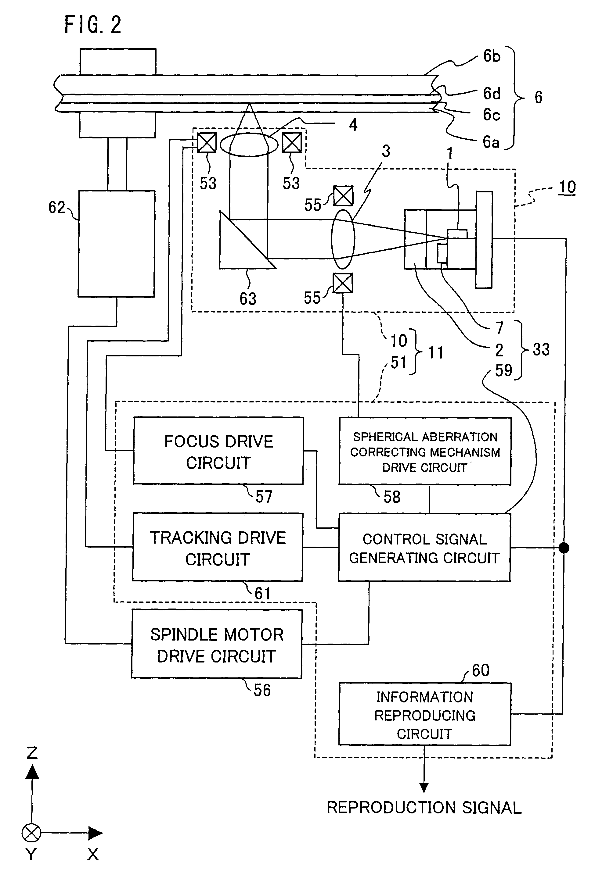
[0069]FIG. 2 is an explanatory view illustrating a general configuration of an optical recording / reproducing apparatus including an optical pickup device of the present invention. As illustrated in FIG. 2, the optical recording / reproducing apparatus of the present embodiment includes: a spindle motor 62 which rotates an optical disk (information storage medium) 6 that is an optical storage medium; a spindle motor drive circuit 56 for controlling the spindle motor 62 to be driven; and an optical pickup device 11.

[0070]The optical pickup device 11 includes: an opt...


PUM

PropertyMeasurementUnit
angleaaaaaaaaaa
wavelengthaaaaaaaaaa

Abstract

An aberration detection device of the present invention is such that an absolute value of detection sensitivity of an aberration error signal is increased, and variation in detection sensitivity of the aberration error signal is little even when displacement between the center of light beam dividing means and the center of a bundle of light beams occurs due to a shift of a condensing optical system at the time of tracking control. A hologram element (2) divides light beams reflected from an information storage medium into at least two positive first order diffracted light beams. The hologram element (2) has a line (D1) extending in a radial direction and passing through an optical axis (OZ) and a division line (D2) having segments at least both ends thereof and a bulge in a center thereof, wherein the segments are substantially parallel to the line (D1), and the bulge (44) bulges toward the periphery of the hologram element (2) so that a top (D5) of the bulge (44) is substantially parallel to the line (D1).

Description

TECHNICAL FIELD[0001]The present invention relates to an aberration detection device for detecting aberration that occurs in a condensing optical system, and an optical pickup device including the aberration detection device. Particularly, the present invention relates to an aberration detection device in which a division pattern of light dividing means is optimized so that detection sensitivity of a spherical aberration error signal does not vary even when the condensing optical system moves at the time of tracking control, and an optical pickup device including the aberration detection device.BACKGROUND ART[0002]With the increase in the volume of information, an optical disk has recently been required to have a higher recording density. A higher recording density of an optical disk has been achieved by increasing a linear recording density in an information recording layer of the optical disk or decreasing a track pitch. To support for the achievement of a higher recording density...

Claims


Application Information

Patent Timeline
Patent Type & Authority Patents(United States)
IPC IPC(8): G11B7/135
CPCG11B7/1353G11B7/13922G11B7/13925G11B2007/0013
Inventor OGATA, NOBUO
Owner SHARP KK
Why Eureka
Try Eureka