Nuclear fuel assembly debris filter bottom nozzle

a technology of fuel assembly and debris filter, which is applied in the field of debris filter bottom nozzle, can solve the problems of fuel assembly damage due to debris, chip and metal particles still remain hidden in the system, and debris tends to lodge in the nozzle, so as to reduce the pressure drop, enhance the manufacturability of this invention, and the effect of reducing the pressure drop

Active Publication Date: 2010-10-26
WESTINGHOUSE ELECTRIC CORP
View PDF26 Cites 13 Cited by
  • Summary
  • Abstract
  • Description
  • Claims
  • Application Information

AI Technical Summary

Benefits of technology

[0008]One embodiment of this invention provides a venturi contour to the flow holes to further reduce the pressure drop across the bottom nozzle plate. A second embodiment further enhances the manufacturability of this invention by creating the venturi contour by chamfering either only the inlet or both the inlet and outlet of the flowthrough holes in the bottom nozzle plate.
[0010]Accordingly, the present invention is directed to a debris filter bottom nozzle useful in a fuel assembly for a nuclear reactor wherein the fuel assembly includes a plurality of nuclear fuel rods, at least a lowermost grid supporting the fuel rods in an organized array and having unoccupied spaces defined therein allowing flow of fluid coolant therethrough. The debris filter bottom nozzle is disposed adjacent to and below the grid and below lower ends of the fuel rods. The bottom nozzle comprises a nozzle plate fixed on support means facing towards a lowermost grid and having defined therethrough a plurality of flow apertures individually sized so that most debris larger in size than the maximum dimension of the unoccupied spaces through the lowermost grid are captured below, within or proximate the aperture outlet orifice. In this way most of the debris being carried by the liquid coolant through the nozzle plate is small enough to pass through the unoccupied grid spaces, whereas most debris being carried by the liquid coolant which is large enough to not pass through the unoccupied grid spaces and collect in the grid, will not pass through the flow apertures or will be retained proximate the outlets of the flow apertures. A reduction in pressure drop across the bottom nozzle plate is achieved by establishing a venturi contour in the flowthrough holes. Further enhancement of the manufacturability and inspectability of the design of this invention is established by providing a chamfer on the outlet side of the flowthrough holes and preferably a double chamfer on the inlet side. Where some reduction in pressure drop is desirable over that achieved in the '507 patent, but the amount of reduction is not critical a further manufacturing cost savings can be achieved by eliminating the outlet chamfer.

Problems solved by technology

Although elaborate procedures are carried out to help assure debris removal, experience shows that in spite of the safeguards used to effect such removal, some chips and metal particles still remain hidden in the systems.
In particular, fuel assembly damage due to debris trapped at the lowermost grid has been noted in several reactors in recent years.
The debris tends to become lodged in the lowermost support grid of the fuel assembly within the spaces between the “egg crate” shaped cell walls of the grid and the lower end portions of the fuel rod tubes.
The damage consists of fuel rod tube perforations caused by fretting of the debris in contact with the exterior of the tube.
Debris also becomes entangled in the nozzle plate holes and the flowing coolant causes the debris to gyrate, which tends to cut through the cladding of the fuel rods.

Method used


Image

  • Nuclear fuel assembly debris filter bottom nozzle
  • Nuclear fuel assembly debris filter bottom nozzle
  • Nuclear fuel assembly debris filter bottom nozzle

Examples


Embodiment Construction

[0018]In the following description, like reference characters designate like or corresponding parts throughout the several views of the drawings. Also in the following description, it is to be understood that such terms as “forward”, “rearward”, “left”, “right”, “upwardly”, “downwardly” and the like are words of convenience and are not to be construed as limiting terms.

Fuel Assembly

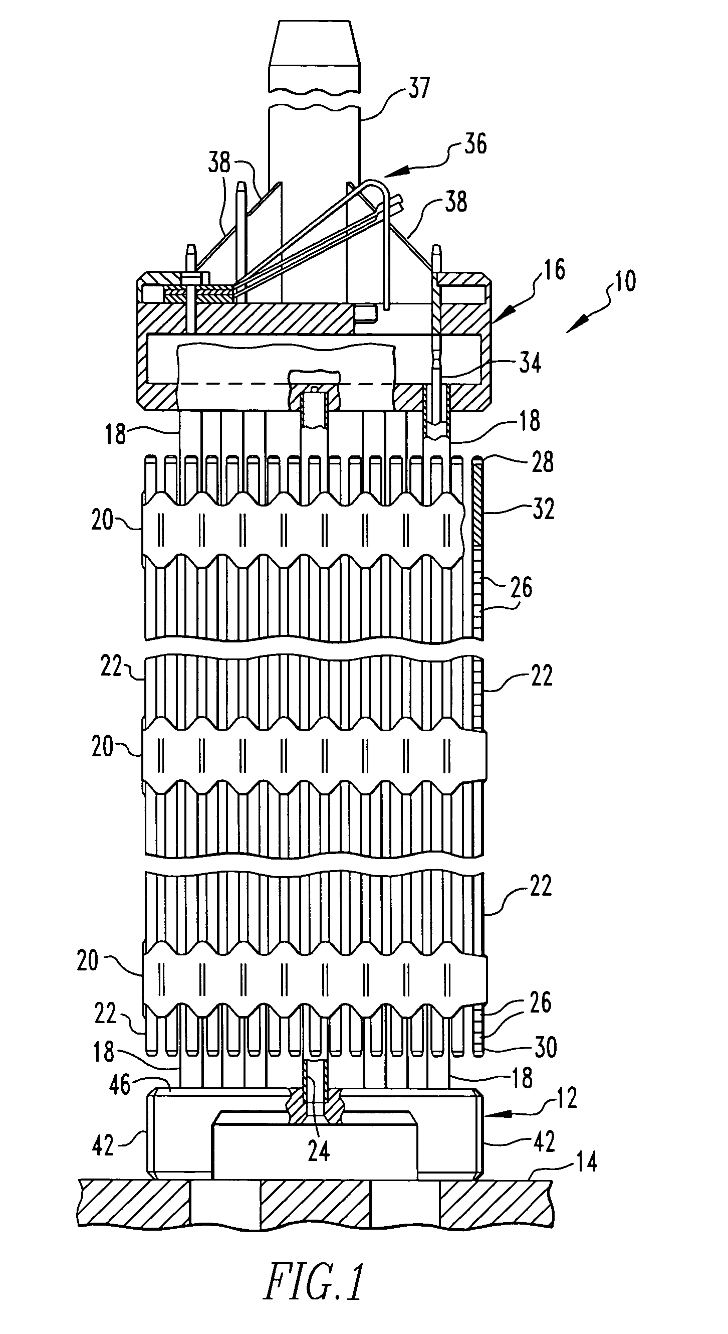
[0019]Referring now to the drawings and particularly to FIG. 1, there is shown an elevational view of the fuel assembly, represented in vertically shortened form and being generally designated by reference numeral 10. The fuel assembly 10 is the type used in a pressurized water reactor and has a structural skeleton which, at its lower end, includes the debris filter bottom nozzle 12 of the present invention (which will be described later in detail). The bottom nozzle 12 supports the fuel assembly 10 on a lower core support plate 14 in the core region of the nuclear reactor (not shown). In addition to the ...


PUM


Abstract

A debris filter bottom nozzle for a nuclear fuel assembly having a support skirt and a top plate. The top nozzle plate has defined therethrough a plurality of flow holes. The axial bore through each flow hole is contoured as a venture. Preferably, the venturi is formed with a double chamfered inlet.

Description

BACKGROUND OF THE INVENTION[0001]1. Field of the Invention[0002]The present invention relates generally to nuclear reactors and, more particularly, is concerned with a debris filter bottom nozzle for a nuclear fuel assembly.[0003]2. Related Art[0004]During manufacturing, subsequent installation and repair of components comprising a nuclear reactor coolant circulation system, diligent effort is made to help assure removal of all debris from the reactor vessel and its associated systems, which circulate coolant throughout the primary reactor coolant loop under various operating conditions. Although elaborate procedures are carried out to help assure debris removal, experience shows that in spite of the safeguards used to effect such removal, some chips and metal particles still remain hidden in the systems. Most of the debris consists of metal turnings, which were probably left in the primary system after steam generator repair or replacement.[0005]In particular, fuel assembly damage ...

Claims


Application Information

Patent Timeline
Patent Type & Authority Patents(United States)
IPC IPC(8): G21C15/00G21C19/28G21C3/30G21C3/04G21C3/32G21C3/33G21C15/06G21C19/30
CPCG21C3/3206G21Y2004/302Y02E30/40Y02E30/30G21C3/04G21C15/06G21C19/30
Inventor BROACH, KIRKLAND D.LUNDE, CARTER E.HAZLETT, PHILLIP L.
Owner WESTINGHOUSE ELECTRIC CORP
Why Eureka
Try Eureka