Pipeline of additional storage elements to shift input/output data of combinational scan compression circuit

a technology of combined scan compression and additional storage elements, which is applied in the direction of detecting faulty computer hardware, error detection/correction, instruments, etc., can solve the problems of large delay of wires in prior art circuits, long wires, etc., and achieve the effect of reducing cycle time and reducing cycle tim

Active Publication Date: 2010-10-26
SYNOPSYS INC
View PDF14 Cites 39 Cited by
  • Summary
  • Abstract
  • Description
  • Claims
  • Application Information

AI Technical Summary

Benefits of technology

[0010]In accordance with the invention, an electronic device is designed to reduce cycle time normally required to shift compressed data between an external interface and a combinational element (compressor / decompressor) of a combinational scan compression (CSC) circuit, by use of one or more storage element(s) that are newly added, in addition to any circuit elements already present in the CSC circuit. Accordingly, one or more storage element(s) that are added in a route (or path), between an external interface and a scan chain, form a pipeline in accordance with the invention that shifts compressed data in stages, across small portions of the route or path. Staged shifting across individual portions as just described can reduce cycle time, e.g. cycle time in some embodiments can be made no more than the longest time required to traverse a stage of the pipeline (that is newly added), if time for data transfer between adjacent scan cells is smaller. The reduced cycle time in turn enables a corresponding increase in frequency at which the compressed data can be shifted through scan chains in the electronic device.

Problems solved by technology

Such distant location of scan chains from the external interface results in long wires and large wire delays in prior art circuits.

Method used


Image

  • Pipeline of additional storage elements to shift input/output data of combinational scan compression circuit
  • Pipeline of additional storage elements to shift input/output data of combinational scan compression circuit
  • Pipeline of additional storage elements to shift input/output data of combinational scan compression circuit

Examples


Embodiment Construction

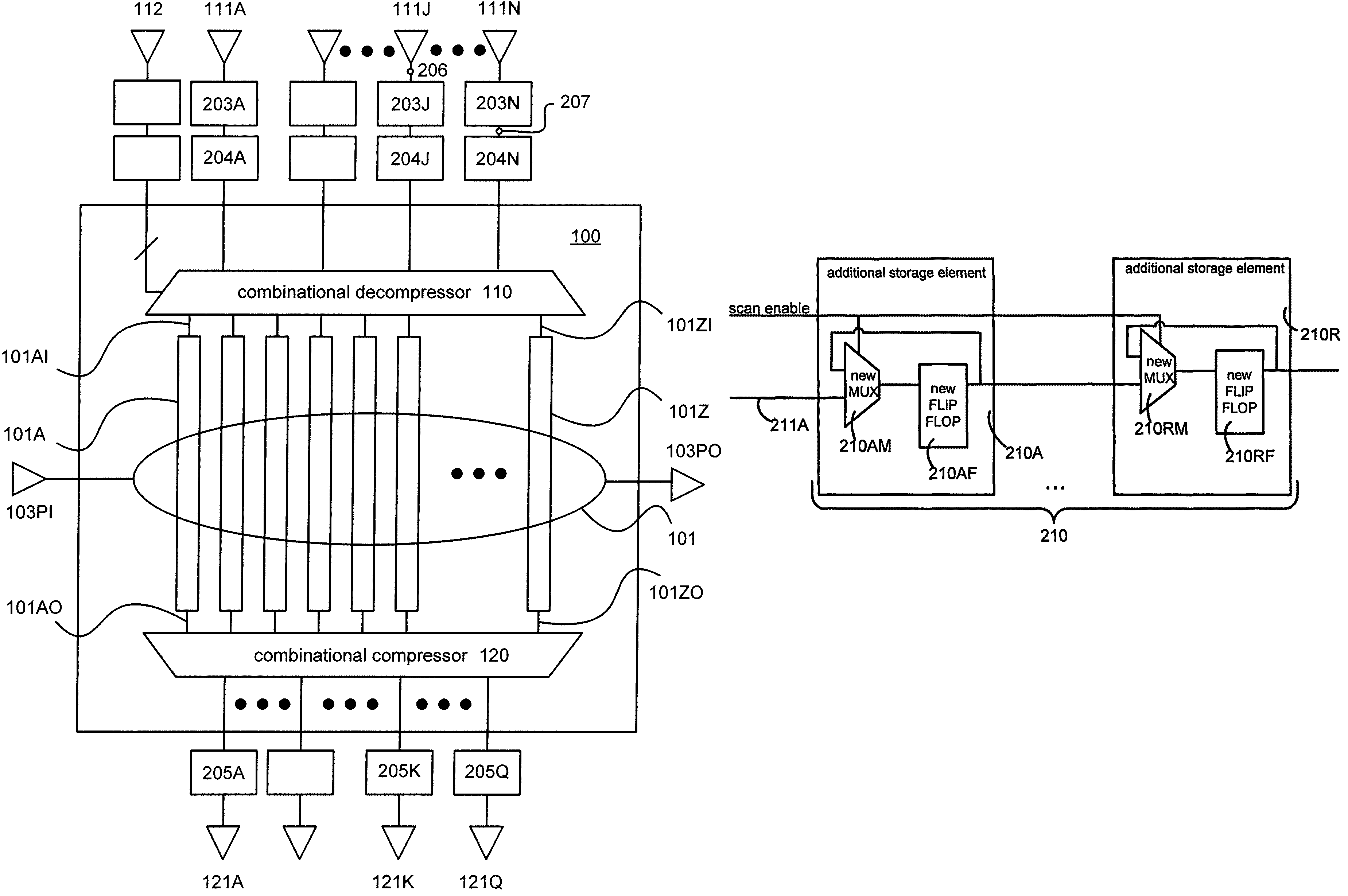
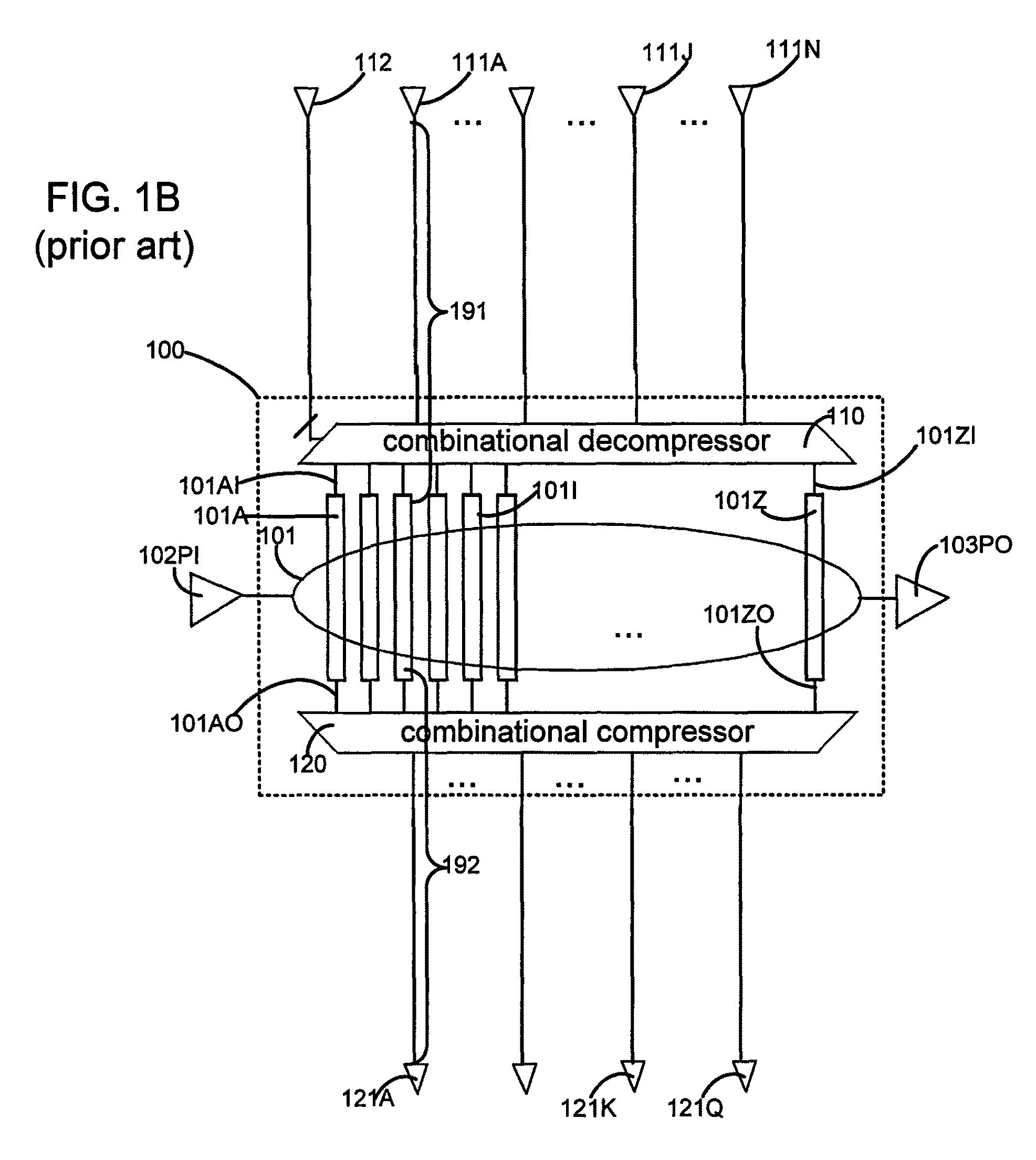
[0041]Cycle time that is normally required to shift compressed data in an ingress path 191 (FIG. 1B) from an input terminal 111A to a first scan cell in a combinational scan compression (CSC) circuit 100, is reduced in one embodiment of the invention as follows. Ingress path 191 (FIG. 1B) is split into two portions thereof, by addition of a storage element 201 that is clocked, as shown in FIG. 2A. In this embodiment, CSC circuit 100 has been kept unchanged during addition of element 201 (and for this reason it is shown hatched in FIG. 2A). Accordingly, storage element 201 is not from within circuit 100.

[0042]More specifically, storage element 201 does not implement any of the features of functionality to be performed by the electronic device. Instead, in the example illustrated in FIG. 2A, storage element 201 is newly added, and is directly connected to a terminal 111A of the external interface, without any combinational element or storage element therebetween. This storage element ...


PUM


Abstract

An electronic device includes a scan-based circuit that includes a combinational decompressor, a combinational compressor, scan chains, and logic which typically includes a number of storage elements. Cycle time normally needed to shift data into or out of a scan cell to / from an external interface of the electronic device is reduced by use of one or more additional storage element(s) located between the external interface and one of the combinational elements (decompressor / compressor). The one or more additional storage element(s) form a pipeline that shifts compressed data in stages, across small portions of an otherwise long path between the external interface and one of the combinational elements. Staged shifting causes the limit on cycle time to drop to the longest time required to traverse a stage of the pipeline. The reduced cycle time in turn enables a corresponding increase in shift frequency.

Description

BACKGROUND[0001]1. Field of the Invention[0002]The invention relates to an architecture for a scan-based integrated circuit (IC). More specifically, the invention relates to a method and circuitry to reduce cycle time in shifting data between an external interface and through a combinational decompressor and / or compressor of a combinational scan compression circuit.[0003]2. Related Art[0004]FIG. 1A illustrates a flow 10 of prior art, for processing a scan test pattern. In flow 10, step 11 sets up the scan chain configuration using flip-flops in the design, thereby identifying the scan cells of the scan chain. Step 12 shifts the scan-in values into the active scan chains. Step 13 exits the scan configuration. Step 14 applies stimulus to the inputs of the logic to be tested (such as logic 101 in FIG. 1B), and measures the outputs. Step 15 pulses the clocks to capture the logic's response in the flip-flops. Step 16 sets up the scan chain configuration. Step 17 shifts the scan-out value...

Claims


Application Information

Patent Timeline
Patent Type & Authority Patents(United States)
IPC IPC(8): G01R31/28G06F17/50
CPCG01R31/318547
Inventor WOHL, PETERWAICUKAUSKI, JOHN ANEUVEUX, FREDERIC J
Owner SYNOPSYS INC
Why Eureka
Try Eureka