Method for suppressing light shift in optical pumping systems

a pumping system and light shift technology, applied in the field of optical pumping, can solve the problems of noise, drift, clock frequency offset, and conventional clocks still experience clock frequency errors, and cannot eliminate light shift, etc., to suppress or eliminate light shift

Inactive Publication Date: 2010-11-02
PRINCETON UNIV +1
View PDF1 Cites 10 Cited by
  • Summary
  • Abstract
  • Description
  • Claims
  • Application Information

AI Technical Summary

Benefits of technology

[0021]The present invention relates to a method and system to suppress or eliminate light shift in an optical pumping system, such as an atomic clock. The method uses modulation of a radiation source, such as a radio frequency (RF) or microwave source, to simultaneously lock the frequencies of both the radiation and the optical pumping sources in order to suppress or eliminate light shift. The method extends the conventional feedback technique of modulating a radiation source to stabilize its frequency to an atomic resonance, to additionally suppress or eliminate the light shift. In one embodiment, the method of the present invention directly utilizes the out-of-phase (quadrature) channel from a lock-in amplifier to additionally lock an optical pumping source to a zero-light-shift frequency, where the in-phase channel is used to lock the frequency of the radiation source to an atomic resonance. A number of advantages of some embodiments include using fewer additional components, offering improved performance, reducing cost, and being more easily miniaturized than conventional systems to eliminate light shift. Additionally, some embodiments of the method can be easily implemented in conventional vapor-cell atomic clocks. The method is useful for atomic frequency standards and other optical pumping systems that experience light shift.

Problems solved by technology

For example, in atomic clocks the light shift leads to errors such as clock frequency offset, noise, and drift.
Conventional vapor-cell clocks, such as the passive rubidium frequency standard, do not eliminate the light shift.
Even with the best lamp sources, conventional clocks still experience clock frequency errors due to the light shift.
However, it has been found that comparable laser pumped standards perform worse than lamp pump standards.
Laboratory laser pumped standards have reached the expected performance, though at the cost of greatly increased complexity.
As a result, laser pumped standards are still not yet commercially available.
The light shift is one of the main reasons for the limited performance of laser pumped standards.
While feasible, this method is not practical for frequency standards or other devices that require continuous measurement and light shift elimination.
Additionally, in practice, other effects such as non-uniform pumping light can introduce nonlinearity into the light shift, which may prevent this method from working.
Additionally, there are semi-continuous methods to eliminate the light shift, which have a main disadvantage in that measurement is interrupted in order to remove the light shift.
The disadvantages of this method are that it requires additional modulation and expensive components, and that it typically is slow.
Disadvantages of these methods are that they require multiple lasers or modulation schemes, and that they add expensive components and additional complexity to the system.
The main disadvantage of such previous methods is that the pumping source frequency is not locked to the zero-shift frequency, which may drift over time.
Therefore, even if the locked pumping source frequency is initially offset to match the zero-shift frequency, the two frequencies will likely drift apart over time.
Other disadvantages of such previous methods are that they require additional modulation, that the locked pumping source frequency varies with different atomic samples, and that the locked pumping source frequency may drift.

Method used


Image

  • Method for suppressing light shift in optical pumping systems
  • Method for suppressing light shift in optical pumping systems
  • Method for suppressing light shift in optical pumping systems

Examples


Embodiment Construction

[0040]Reference will now be made in greater detail to embodiments of the invention, examples of which are illustrated in the accompanying drawings. Wherever possible, the same reference numerals will be used throughout the drawings and the description to refer to the same or like parts.

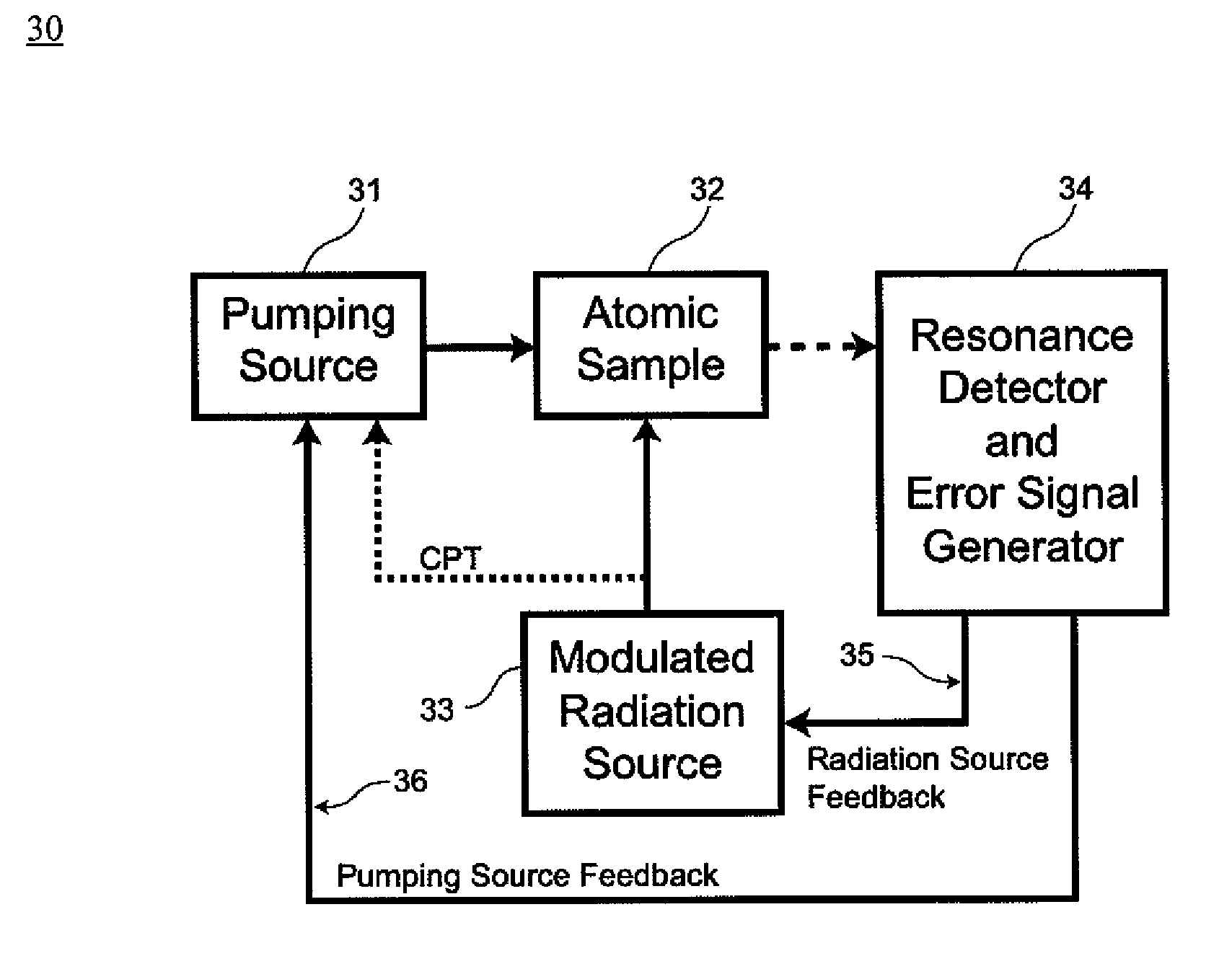
[0041]FIG. 2 is a flow diagram of a method for suppressing light shift in an optical pumping system 20. In block 21, an atomic sample of an optical pumping system is pumped by a pumping source in an optical pumping system. Examples of optical pumping systems include atomic clocks, atomic magnetometers, masers, spectroscopy systems associated with optical pumping, and other atomic systems associated with optical pumping. Examples of atomic samples include atomic vapor cells, atomic beams, and atom traps. An example of a pumping source is a laser. In block 22, atomic resonances are excited with a modulated radiation source. Examples of modulation methods include frequency or phase modulation methods. Ex...


PUM


Abstract

The present invention relates to a method and system to suppress or eliminate light shift in an optical pumping system, such as an atomic clock. The method uses modulation of a radiation source, such as a radio frequency or microwave source, to simultaneously lock the frequency of the radiation source to an atomic resonance and lock the frequency of the optical pumping source in order to suppress or eliminate light shift. In one embodiment, the method of the present invention directly utilizes the out-of-phase channel of a lock-in amplifier to additionally lock an optical pumping source to a zero-light-shift frequency, where the in-phase channel is used to lock the frequency of the radiation source to an atomic resonance.

Description

STATEMENT OF GOVERNMENT FUNDED RESEARCH[0001]This work was supported by the Air Force Office Scientific Research 245-6581 and Department of Defense NDSEG Fellowship. Accordingly, the Government has certain rights in this invention.BACKGROUND OF THE INVENTION[0002]1. Field of the Invention[0003]The present invention relates to the field of optically pumped atomic frequency standards and other optical pumping systems, and more particularly to a method and system for suppressing or eliminating light shift in an optical pumping system by using a modulated radiation source for simultaneously locking the frequency of the radiation source to an atomic resonance and locking the frequency of the optical pumping source.[0004]2. Description of the Related Art[0005]Two examples of optical pumping systems are atomic frequency standards and atomic magnetometers. Atomic frequency standards, or atomic clocks, are applied in various systems that require extremely accurate frequency measurements. Ato...

Claims


Application Information

Patent Timeline
Patent Type & Authority Patents(United States)
IPC IPC(8): H03L7/26
CPCG04F5/145H03L7/26
Inventor MCGUYER, BART H.JAU, YUAN-YUHAPPER, WILLIAM
Owner PRINCETON UNIV
Why Eureka
Try Eureka