Shift register circuit and image display apparatus containing the same

a technology of shift register and image display apparatus, which is applied in logic circuits, digital storage, instruments, etc., can solve problems such as signal delay increase, delay in output signal, display problem, etc., and achieve the effect of fast operation of shift register circui

Active Publication Date: 2010-11-02
TRIVALE TECH
View PDF23 Cites 62 Cited by
  • Summary
  • Abstract
  • Description
  • Claims
  • Application Information

AI Technical Summary

Benefits of technology

[0012]It is an object of the present invention to achieve a faster operation of a shift register circuit which is capable of individually outputting a signal (carry signal) for driving another shift register circuit and a signal (gate line driving signal) for driving a gate line, by suppressing an influence between the two signals.
[0015]It is assumed, for example, that a plurality of shift register circuits of this present invention are connected in cascade to form a gate line driving circuit of a display apparatus. When a signal of the first output terminal of each shift register circuit drives a gate line and a signal of the second output terminal drives another shift register circuit, even if a delay is caused in the signal of the first output terminal by a load on the gate line, the speed of the second output signal can be maintained. It is therefore possible to ensure a faster operation of the gate line driving circuit.

Problems solved by technology

With this constitution, however, a load on the gate line exerts an influence upon the input terminal of the succeeding-stage unit shift register, to thereby cause a delay in an output signal.
The signal delay increases as the stage becomes posterior in the cascade connection, and sometimes, this eventually causes a problem in display.
For this reason, when the rising speed of the gate line driving signal becomes lower due to variations in ambient temperature, threshold voltage of a transistor or the like, the rising speed of the carry signal accordingly becomes lower and this disadvantageously makes it difficult to perform a high-speed operation.

Method used


Image

  • Shift register circuit and image display apparatus containing the same
  • Shift register circuit and image display apparatus containing the same
  • Shift register circuit and image display apparatus containing the same

Examples


Embodiment Construction

[0035]Preferred embodiments of the present invention will be discussed hereinbelow, referring to the accompanied drawings. To avoid repeated and redundant description, elements having the same or corresponding functions are represented by the same reference signs in the drawings.

The First Preferred Embodiment

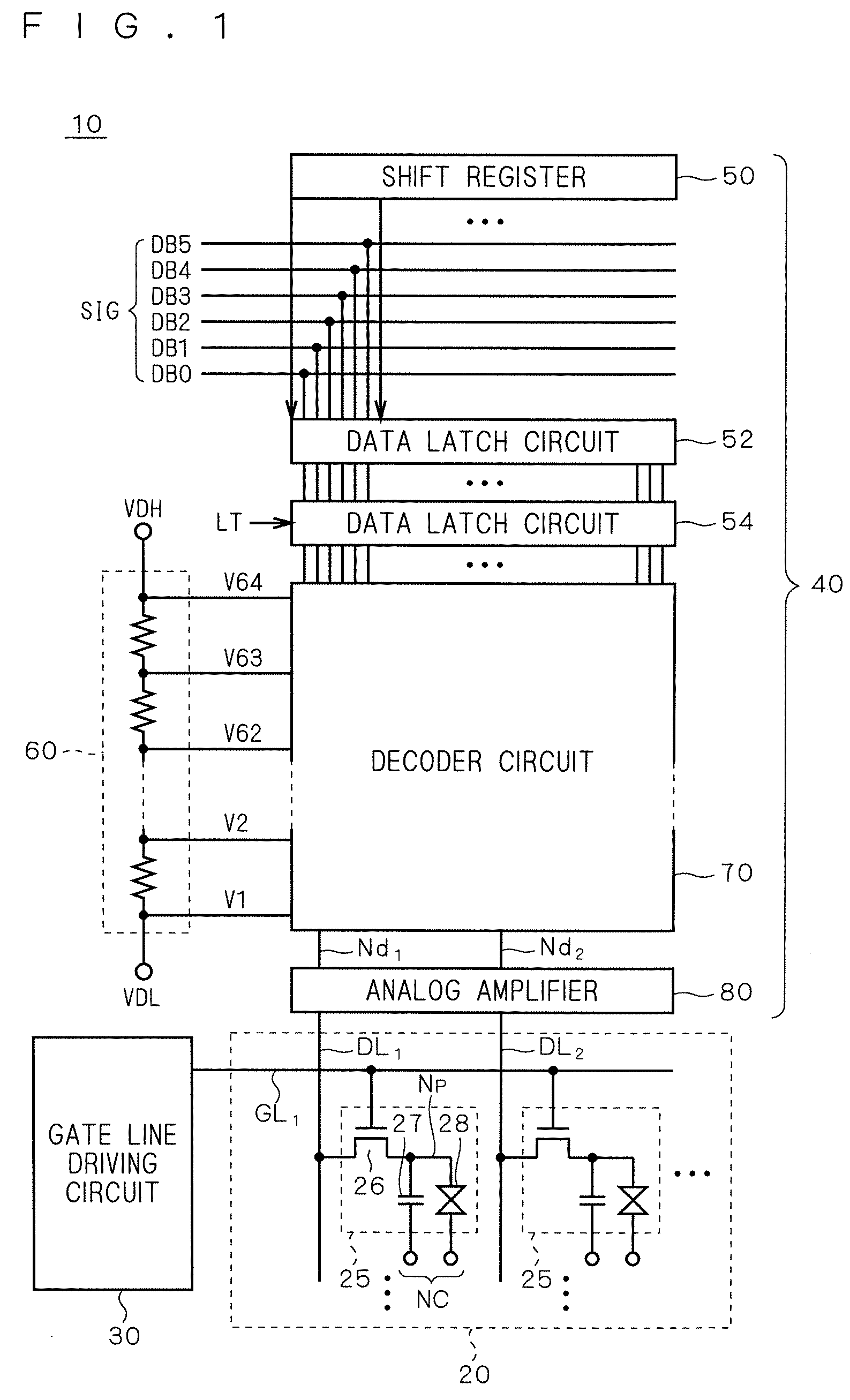
[0036]FIG. 1 is a schematic block diagram showing a constitution of a display apparatus in accordance with the first preferred embodiment of the present invention. As a typical example of the display apparatus, in FIG. 1, an overall constitution of a liquid crystal display 10 is shown.

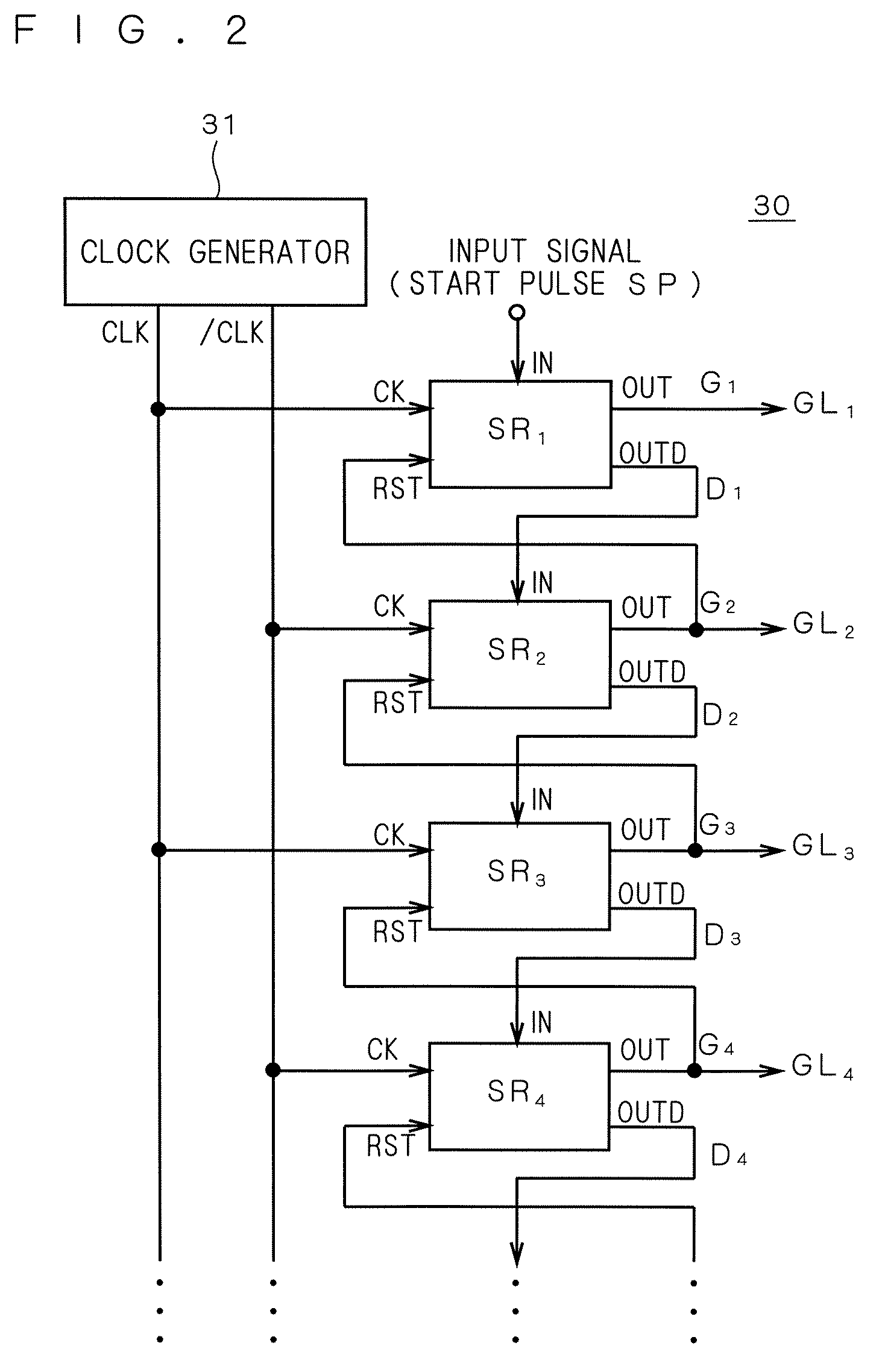
[0037]The liquid crystal display 10 comprises a liquid crystal array part 20, a gate line driving circuit (scanning-line driving circuit) 30 and a source driver 40. As will be described later explicitly, a shift register of the first preferred embodiment is mounted on the gate line driving circuit 30.

[0038]The liquid crystal array part 20 includes a plurality of pixels 25 which are arranged in a ma...


PUM


Abstract

A shift register circuit comprises a first transistor between a gate line output terminal and a clock terminal, a second transistor between the gate line output terminal and a first power supply terminal, a third transistor between a carry signal output terminal and the clock terminal and a fourth transistor between the carry signal output terminal and the first power supply terminal. Gates of the second and fourth transistors are connected to each other. A fifth transistor connected between a gate of the first transistor and a second power supply terminal and a sixth transistor connected between a gate of the third transistor and the second power supply terminal have gates both of which are connected to an input terminal. With this constitution, it is possible to suppress an influence between two synchronous output signals outputted from the shift register circuit.

Description

BACKGROUND OF THE INVENTION[0001]1. Field of the Invention[0002]The present invention relates to a shift register circuit, and more particularly to a shift register circuit used as a scanning-line driving circuit in an image display apparatus, or the like, which is formed only of field effect transistors of the same conductivity type.[0003]2. Description of the Background Art[0004]In an image display apparatus (hereinafter, referred to as “display apparatus”) such as a liquid crystal display, a plurality of pixels are arranged in a matrix in a display panel and a gate line (scanning line) is provided for each row of pixels (pixel line) in the display panel. In a cycle of one horizontal period of a display signal, the gate lines are sequentially selected and driven, to update a displayed image. As a gate line driving circuit (scanning-line driving circuit) for sequentially selecting and driving the pixel lines, i.e., the gate lines, a shift register may be used, which performs a roun...

Claims


Application Information

Patent Timeline
Patent Type & Authority Patents(United States)
IPC IPC(8): G09G3/36
CPCG09G3/3648G09G3/3677G11C19/184G09G3/3688G09G2310/021G09G2310/0251G09G2310/027G09G2320/0252G09G3/20G09G3/36G11C19/00H03K19/00
Inventor TOBITA, YOUICHIMURAI, HIROYUKI
Owner TRIVALE TECH
Why Eureka
Try Eureka